Configure the Mapping
Version 25.3.9469
Version 25.3.9469
Configure the Mapping
The following image of a completed XML Map mapping page has been annotated to explain each element on the screen (the EDI document mapping is similar). Each number corresponds to a description below.
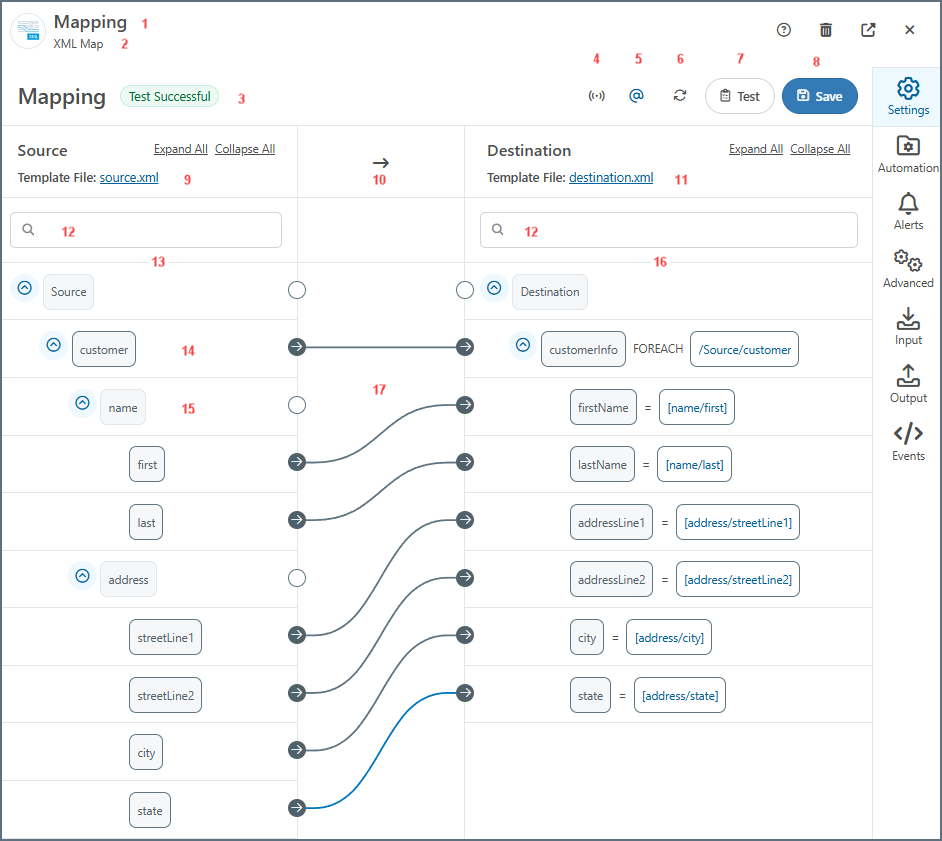
- The document or connector name.
- The connector type.
- Test status of the mapping. Values are Test Successful, Tested with Errors, or Not Tested.
- Toggles XML streaming on or off (it is on by default). When on, the mapping engine drops the Document Object Model (DOM) for the current iteration of the top-most
Foreachin the mapping after completing the loop. This can significantly improve performance for large XML documents. In situations where the mapping engine cannot resolve the mapping, it automatically toggles XML streaming off. - Toggles between regular and compact views of the mapping (the compact view can be helpful with large template files).
- Toggles whether to show or hide the XML attributes.
- Refreshes the mapping.
- Launches the AI-Assisted Mapping tool.
- Opens the Test Mapping page. The test result is shown in #3. (See Testing Mappings for more information.)
- Saves the mapping.
- The selected source template file.
- The direction of the mapping.
- The selected destination template file.
- Search bars on the source and destination sides.
- Structure of the source XML.
- The name of a Parent node.
- The name of a Leaf node.
- The structure of the destination document.
- Completed mappings.
Understanding Source and Destination
To define a mapping, click and drag a node from the left pane onto its corresponding object on the right. When a node is selected, the lines for its connections are blue, and all other lines are black.
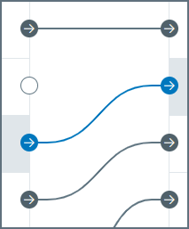
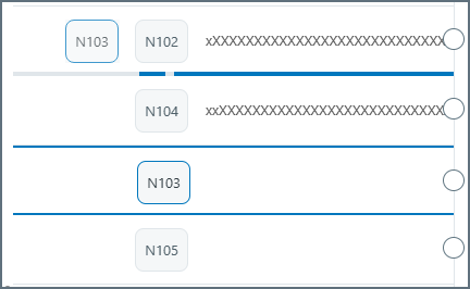
When you drag-and-drop elements in a source or destination tree, one or both of the blue lines on the drop node is darker/active, as shown in the following image. If both are active, the node being dragged is created as a sibling of the drop node. If only the right line is active, the node being dragged is created as a child of the drop node. In the following image, the N103 node is being moved from below N104 to be a direct sibling of the N102 node, so both blue lines are highlighted.
To remove a mapping, hover over one end of the mapping and click Remove Mapping. When you have finished the mapping definition, click Save.
Mapping Nodes
Parent and leaf nodes define the hierarchical structure of XML data, where parent nodes group related elements and leaf nodes represent the actual data values to be mapped.
- Parent: A node in the XML mapping tree that contains leaf elements but does not have a value. Parent nodes are similar to table nodes in the TPMC.
- Leaf: A node that contains a value but does not have child elements. Leaf nodes are similar to column nodes in the TPMC.
The following sections describe parent and leaf node options in detail.
Parent Nodes
XML Parent Element
As mentioned earlier, the tree in the mapping editor has two types of nodes:
- Parent nodes have children but no value.
- Leaf nodes have a value but no children.
Parent nodes in the source can only be dragged onto parent nodes in the destination.
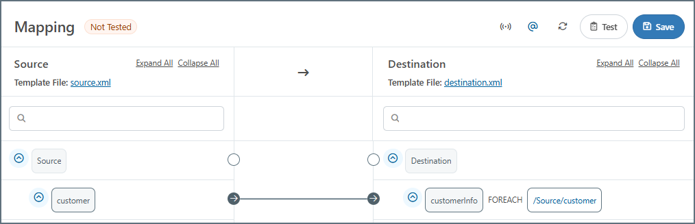
Dragging a source parent onto a destination parent establishes a Foreach relationship between the source and destination nodes. This means that each occurrence of the source element produces a corresponding destination element, including all of the destination element’s children.
Once a Foreach relationship is established, an xpath appears in the destination, as shown in the image below. Elements at this path in the input XML result in a new instance of the output node and its children. In other words, a Foreach relationship instructs the mapping engine to loop over a given xpath in the source and produce the mapped destination structure for each element it finds. The xpath in the destination tree view is the xpath over which the mapping engine loops.
Virtual Loop
A virtual loop is a special node you can add to the destination structure that does not directly appear in the output XML. It provides an opportunity to implement logic that affects the appearance and/or values of other (non-virtual) nodes in the output.
It functions the same as a Foreach mapping between parent nodes, except that the parent node does not appear in the output XML. This allows you to flatten repeated elements in the source into a non-hierarchical structure in the destination. This is easiest to understand via an example.
Take the following input XML:
<!-- example input -->
<Items>
  <DataReading>
    <Temperature>212.5</Temperature>
  </DataReading>
  <DataReading>
    <Temperature>9.2</Temperature>
  </DataReading>
  <DataReading>
    <Temperature>5.1</Temperature>
  </DataReading>
</Items>
This needs to be mapped to a flat structure that includes all of the DataReading data:
<!-- desired output -->
<Items>
  <OutputData>
    <TemperatureReading>212.5</TemperatureReading>
    <TemperatureReading>9.2</TemperatureReading>
    <TemperatureReading>5.1</TemperatureReading>
  </OutputData>
</Items>
You can accomplish this by establishing a Foreach relationship with a loop node in the destination corresponding to each DataReading element in the source:
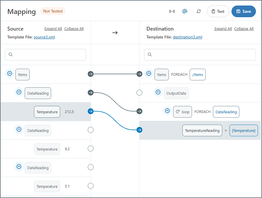
If the Foreach relationship was established between DataReading and OutputData, then the OutputData element would be repeated in the result. The loop node avoids this repetition of hierarchy and flattens the value into the single OutputData element.
To add the loop node shown in the example above, follow these steps:
- Right-click or click the ellipses on the TemperatureReading node and choose Add Node > Add Loop. Give the loop a meaningful name, then click the checkmark to save.
- Drag the source DataReading node onto the loop to create the Foreach relationship.
- Map the source Temperature node to the destination TemperatureReading node.
Virtual Condition
A virtual condition groups output elements together based on a shared condition. All children of the condition node appear in the output if the condition is true, and do not appear if the condition is false.
This is functionally equivalent to adding the same condition to each of the individual nodes independently. For conditions that affect many different nodes, it is usually more convenient to create a single condition node and then make all of the relevant output nodes a child of the condition node.
To create a condition virtual node, follow these steps:
- Right-click or click the ellipses on a destination node and choose Add Node > Add Condition.
- Click the funnel icon next to the new condition to create the condition rules. See Using the Condition Editor for details.
Leaf Nodes
XML Leaf Element
Dragging a source leaf onto a destination leaf instructs the mapping engine to populate the destination element with the value from the source element. After dragging-and-dropping onto the destination node, the xpath from which values will be read appears in the destination tree view, as shown in the image below.
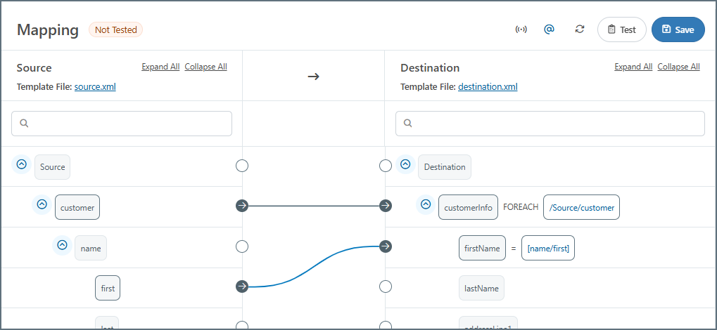
The xpaths displayed in the destination tree view are either absolute or relative. Absolute xpaths begin with a slash (/) and describe the entire xpath in the source, beginning from the root of the document. Relative xpaths do not begin with a slash, and they are relative to a Foreach loop set in a parent node.
A relative xpath can be relative to multiple Foreach loops (as long as the element has multiple parents that each have a Foreach relationship mapped). To find the absolute xpath for any given relative xpath, simply concatenate each parent’s Foreach xpath, starting from the top of the document, until you reach the current node.
XML Attribute
To work with XML attributes in addition to element values, make sure the Show Attributes setting at the top of the mapping page is toggled on ( ). Once enabled, the editor displays any attributes detected as a child of the element the attribute belongs to.
All XML attributes names are prefixed with @ (the @ symbol is not a valid character in an XML element name). This character is purely for display, and is stripped away when reading or writing attributes.
Reading XML Attributes from the Source
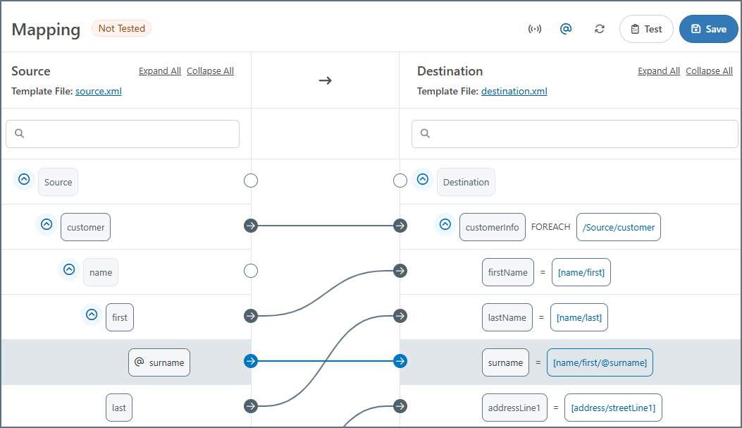
Once the Show Attributes toggle is enabled, any attributes in the XML source are displayed as nodes in the mapping editor. You can drag-and-drop these values onto the destination just like any other node. The nodes show the @ prefix indicating that they are XML attributes and not XML elements, as shown in the following image.
Writing XML Attributes in the Destination
Destination templates that include XML attributes display the attribute nodes as children of the element they belong to, and these nodes can be mapped just like any other value.
To add new attributes to a destination node, right-click or click the ellipses on the node and choose Add Node > Add Attribute.
Note: Attribute names always begin with the @ prefix (this character is not included in the output XML).
Headers
Header nodes enable you to map values as headers on the output message of the mapping. These header nodes are not included in the output XML, but are added as metadata message headers on the output message. These headers stay with the message throughout the entire flow and their values can be referenced by any downstream connector as needed, which makes it easy to track the progress of data through the application. Header nodes are automatically added to the Message Headers tab in the node value editor. To add a header node, right-click or click the ellipses on an existing node and choose Add > Add Header.
Header nodes are not added to Tracked Headers. You can add non-header destination nodes to the tracked headers by clicking the ellipses on a node and choosing Add Tracking. See Message Headers for more information.
Code Script
A code script virtual node provides an opportunity to write custom ArcScript that does not need to return an output value. Often, these nodes use variables or the special _map item to store values that need to be referenced later in the mapping, but do not need to be output in the current context.
For example, the scenario described in the Map Item section is a good candidate for a virtual code script node. The sum of the line item costs needs to be returned as output outside of the Foreach loop where it is calculated. So, a virtual code script node in the Foreach loop can calculate the value and not output it. Then this value can be referenced as output in a non-virtual node outside the loop.
To create a code script virtual node, follow these steps:
- Right-click or click the ellipses on a destination node and choose Add Node > Add Code Script.
- Enter a Script Name.
- Supply the script. The editor validates your expression as you type, so if you see an Invalid Script message, you have a syntax issue. When you are finished, click Add Script.
Variable Nodes
It can be useful to set variables at one point in the mapping and reference those variables again later in the mapping. For details and an example, see Variables.
Node Options
To work with individual nodes, hover over the node then right-click or click the ellipses to select from a set of additional options. The options vary according to the type of node you are working with. This section describes the options available when you are working with parent, leaf, or document nodes. See Table Nodes and Column Nodes for details on those node types.
- Rename Node lets you change the name of the node.
- Edit XPath lets you edit the node XPath (only on elements already mapped as
Foreach). - Delete Node lets you delete the node from the document.
- Add Node
- Add Sibling adds a node at the same level as the selected node.
- Add Attribute adds an attribute to the selected node.
- Add Child adds a node as a child of the selected node.
- Add Header creates a header node that you can map a value to. The mapped value is not included in the output file but is added as a header on the mapping output message.
- Add Loop creates a loop node above the selected node and that node becomes nested within the loop node. See Mapping Loops for more information.
- Add Condition opens the Condition Editor where you can add conditions so that data is only upserted to the destination if the condition is true.
- Add Code Script creates a new script node as a sibling of the target element. Use the Add Script window to name the script and supply custom ArcScript.
- Add Variable creates a variable node below the selected node. See Variables for more information.
- Cut Node cuts the selected node from its current location.
- Copy Node copies the selected node.
- Paste as Child pastes the cut or copied node as a child of the selected node.
- Add Tracking adds tracked headers to the mapping. When a node has tracking enabled, it displays a compass icon.
You can also use Edit Node to open the Edit Node Value page. See Using the Node Value Editor.
AI-Assisted Mappings
Once you have set up AI Settings on your instance and you have uploaded or set your source and destination template files, you can use OpenAI or Ollama to assist with building the mappings. This features addresses mapping configuration challenges by providing intelligent mapping suggestions, which make it significantly easier to create accurate data transformations.
To have AI generate the entire mapping, click the ![]() icon at the top of the page.
icon at the top of the page.
Alternatively, you can have AI generate mappings at the node level. Right-click or use the ellipses on a parent node on the source or destination side, choose AI Assisted Mapping, then one of the following options:
- Map Node
- Map Child Node
- Node and Child Nodes
After AI has generated the mappings, you can adjust them if necessary.
Mapping Loops
Creating a parent node mapping establishes a Foreach relationship between the source and destination nodes. This means that each occurrence of the source element produces a corresponding destination element, including all of the destination element’s leaf nodes. Creating a leaf node mapping instructs the mapping engine to populate the destination element with the value from the source element.
Map parent nodes (Foreach loops) before leaf nodes. Establishing the loop relationships requires an understanding of the source and destination XML structures: whenever a repeated element in the source should result in a repeated element in the destination, those elements should be mapped together in a Foreach relationship.
Within a Foreach loop, leaf element xpaths are relative to the mapped Foreach xpath.
As a very simple example, consider the following source and destination XML, where a nested XML structure should be converted into a flat XML structure:
<Source>
  <customer>
    <name>
      <first></first>
      <last></last>
    </name>
    <address>
      <streetLine1></streetLine1>
      <streetLine2></streetLine2>
      <city></city>
      <state></state>
    </address>
  </customer>
</Source>
<Destination>
  <customerInfo>
    <firstName></firstName>
    <lastName></lastName>
    <addressLine1></addressLine1>
    <addressLine2></addressLine2>
    <city></city>
    <state></state>
  </customerInfo>
</Destination>
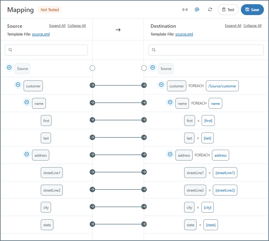
Each repetition of the customer element in the source should result in a customerInfo element in the destination, so these parent elements should be mapped together to form a Foreach relationship. Then, the mapping for each Leaf element is simple:
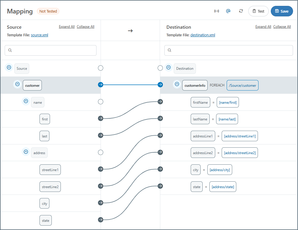
Notice that the xpaths for the leaf elements are relative to the xpath in the parent element (the xpath that defines the Foreach relationship).
Mapping Multiple Loops
Mappings often require multiple Foreach loop relationships within the same document. The principle for mapping loops remains the same: any repeated parent elements in the source that should generate repeated elements in the destination should be mapped as a loop. Map outer loops before inner loops (in other words, start at the top of the structure and work down). All looping relationships should be mapped before any leaf elements are mapped.
As a common example, consider mapping an incoming Purchase Order report to a destination database. Such a mapping contains two distinct element structures that might repeat, so each requires a Foreach relationship: (1) a single report might contain multiple individual orders, and (2) an individual order might contain multiple line items.
Example Input
The source template structure might look like this:
<OrderReport>
  <WebOrder>
    <CustomerName>John Doe</CustomerName>
    <PurchaseDate>12/21/22</PurchaseDate>
    <Line>
      <ItemName>Hammer</ItemName>
      <ItemCost>1500</ItemCost>
      <ItemQuantity>1</ItemQuantity>
      <ItemDescription>Standard claw hammer</ItemDescription>
    </Line>
    <Line>
      <ItemName>Nail</ItemName>
      <ItemCost>10</ItemCost>
      <ItemQuantity>20</ItemQuantity>
      <ItemDescription>Ten penny nails</ItemDescription>
    </Line>
    <Subtotal>1700</Subtotal>
    <TaxPercent>4</TaxPercent>
  </WebOrder>
</OrderReport>
This example includes only one WebOrder element for brevity, but the mapping should handle cases where multiple WebOrder sections are included in the same OrderReport.
Example Output
The output of this mapping should match the XML model of a database insert. The XML model of a database insert is created automatically by a database connector (for example, the MySQL, SQLite, and CData connectors), and the Template Files from Database Connectors section describes how these XML models can be used as template files in the XML Map Connector.
Proper database design suggests that the data should be inserted into two separate tables, one for Orders and one for Line Items. Generating an appropriate input mapping for this approach can result in a template structure like this:
<Items>
  <Order>
    <FirstName></FirstName>
    <LastName></LastName>
    <Date></Date>
    <OrderLine>
      <Name></Name>
      <Desc></Desc>
      <Price></Price>
      <Amount></Amount>
    </OrderLine>
  </Order>
</Items>
In this example, the Order element represents an insertion into an Orders table, and the OrderLine element represents an insert into a Line Items table. Templates are generated with only one element representing each table, but the Foreach relationships established during the mapping ensure that the appropriate number of inserts are created.
The other children of Order (FirstName, LastName, Date) represent columns in the Orders table, and the children of OrderLine (SKU, Price, etc) represent columns in the Line Items table.
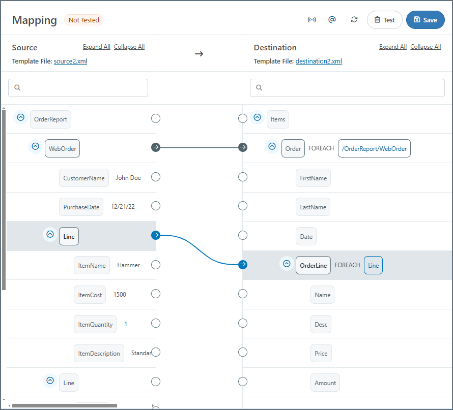
Establishing the Looping Relationships
A WebOrder element in the Source should result in a new insert into the Orders table, so it should be dragged onto the Order element in the Destination. Similarly, a Line element in the Source should result in a new insert into the Line Items table, so it should be dragged onto the OrderLine element in the Destination.
After establishing these two Foreach relationships, the mapping editor should look like this:
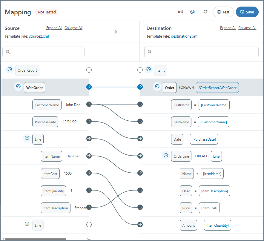
After the loop relationships are established and any unnecessary destination elements are removed, you can map the leaf elements to fill in the destination values:
Unnecessary Parent Nodes
When establishing a Foreach relationship, only a single instance of the mapped elements needs to exist in the source and destination file. In other words, the Foreach relationship takes care of ensuring that the number of output elements matches the number of corresponding input elements.
To make this clear, imagine in the Mapping Loops example that the source file (the template for the input XML) had multiple sets of customer element groups. Establishing a single Foreach relationship between customer (source) and customerInfo (destination) ensures that the number of customerInfo element groups matches the number of customer element groups for any input file. Since it only takes one customer element to establish this Foreach relationship, all other customer elements are irrelevant to the mapping and can be ignored or deleted.
Similarly, if the destination file in the above example had multiple customerInfo elements, all but one should be deleted. The Foreach relationship between customer and customerInfo ensures that the appropriate number of customerInfo element groups appear in the XML output.
Testing Mappings
Use the Test Mapping button to check that your mappings work as you expect. The test populates the destination elements with values from the source files, as shown below:
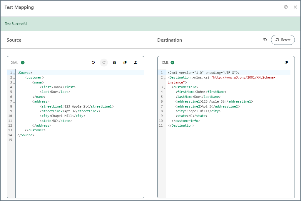
If a test fails, the Destination pane provides an explanation of the failure.
Mapping Best Practices
Foreach loops are a powerful tool for mapping repeated elements in a destination file. However, it is important to follow these best practices to ensure proper functionality and avoid performance issues:
-
When using large XML files, avoid mapping the entire file as a Foreach loop. This style of mapping instructs the mapping engine to load the entire file into memory, which can result in long processing times.
-
Instead, it is best practice to keep the full source document structure in mind, and only create Foreach relationships for elements that are known to be repeated (as described above in Establishing the Looping Relationships). This practice minimizes the performance impact associated with Foreach relationships.