Document Workflow Mappings
Version 24.3.9159
Version 24.3.9159
Document Workflow Mappings
An important component of the TPMC is configuring the mapping between the incoming or outgoing EDI document and the connector where the data is stored or sent to.
Incoming mappings rely on receiving EDI documents from a partner over an MFT protocol, translating them from EDI to XML using an EDI standard, then mapping them to a destination connector such as a database.
Outgoing mappings rely on pulling data as XML from a source connector (such as a database), mapping that data to an XML representation of an EDI standard, converting the XML to EDI, then sending the EDI document out to a partner over an MFT protocol.
Document workflows are defined in two ways.
- From the Partners tab, click the name of a partner, then choose the Workflows tab. See Select or Add Documents for instructions on how to add documents and launch a workflow.
- From the Documents tab, click the name of an existing document, or choose Add Document to create a new one. See Creating a Document from the Documents Tab for instructions on how to add a document and launch a workflow.
Add Document Workflow
Defining document workflows includes the following steps:
- Complete the Add Document Workflow screen.
- When you add a document from the Partners tab, click Add Workflow to launch the document workflow. In this case, the fields on the Add Document Workflow screen are prefilled. You can change the document name, but all other fields are fixed.
- When you add a document from the Documents tab, you must manually complete the fields on the Add Document Workflow screen.
- Select and configure the source or destination connector
- Configure the mapping. Mapping is applicable for all connectors except File, AMQP, and Apache Kafkawhich do not use mapping. See Document Workflow Without Mapping for more information.
Select and Configure the Source or Destination
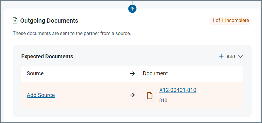
When you create an incoming document, you must specify the destination connector where the data will be added. When you create an outgoing document, you must specify the source connector to pull the data from. The available connectors are the Arc Database and Other connectors, and the File connector.
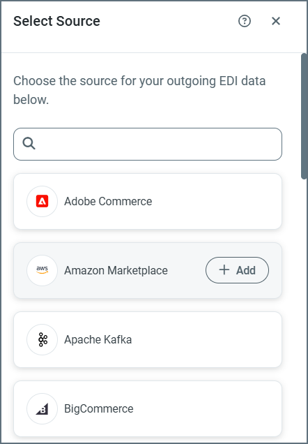
The following images show configuring a source for an outgoing document, but the same principles apply for incoming document destinations. In this example, the source is being defined from a partner’s Workflow tab, but you can achieve the same result from the Documents tab.
-
From the Workflow tab, click Add Source.
-
Highlight a connector in the Select Source list and click Add.
-
Use the plus sign to create a new Connection, or use the dropdown to select an existing one.
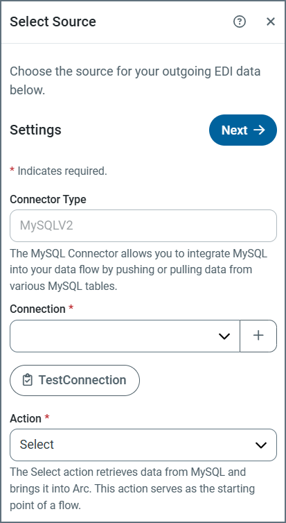
- When you add a new connection, complete the following fields in the Add Connection window:
- Name
- Server
- Port
- User
- Password
- AWS Access Key (optional)
- AWS Secret Key (optional)
- AWS Role ARN (optional)
- Click Test Connection.
- The only action available for an outgoing document is
Select, so when you have added and tested your connection, click Next. (The action for an incoming document isUpsert. See Actions for more information.)
This opens the Action connector configuration tab, where you complete the mappings. See Configure the Mapping for instructions on how to use this tab.
Notes:
- Use the other configuration tabs (such as Settings and Automation) to complete the connector configuration. For details on the configuration options, click the question mark help icon to open the connector documentation.
- If you need to modify the connection after the original setup, use the Connection field on the Settings tab.
Configure the Mapping
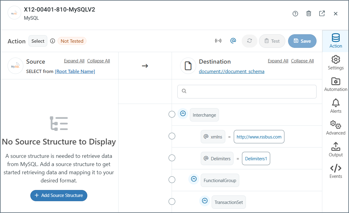
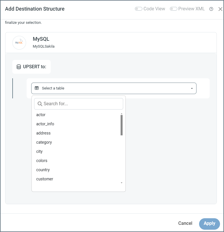
Once you have established the connection, you must select the table(s) that you need to map. If you’re creating an incoming document, click Add Destination Structure. If you’re creating an outgoing document, click Add Source Structure. This example shows adding a destination structure.
- Select a table from the dropdown.
- To add more tables to the mapping, click the link to the first table, then click the Add Child Table arrow and select the next table.
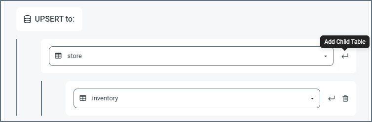
- Repeat these steps until you have added all the required tables. As you make changes, the mapping page displays the latest table structure.
The mapping page enables you to create the links between the EDI document and the source or destination connector. For incoming documents, the EDI document structure is in the left pane and the connector table structure is in the right pane. For outgoing documents it’s the reverse, as you can see in the annotated image below.
To define a mapping, click and drag a node from the left pane onto its corresponding object on the right. To remove a mapping, hover over one end of the mapping and click Remove Mapping. When you have finished the mapping definition, click Save.
Note: To edit a previously saved mapping, click EDI > Documents, then click the document name. In the Document Workflow section, click the link to the connector in the Document Destination (for incoming documents) or the Document Source (for outgoing documents).
The following image of a completed mapping has been annotated to explain each element on the screen. Each number corresponds to a description below.
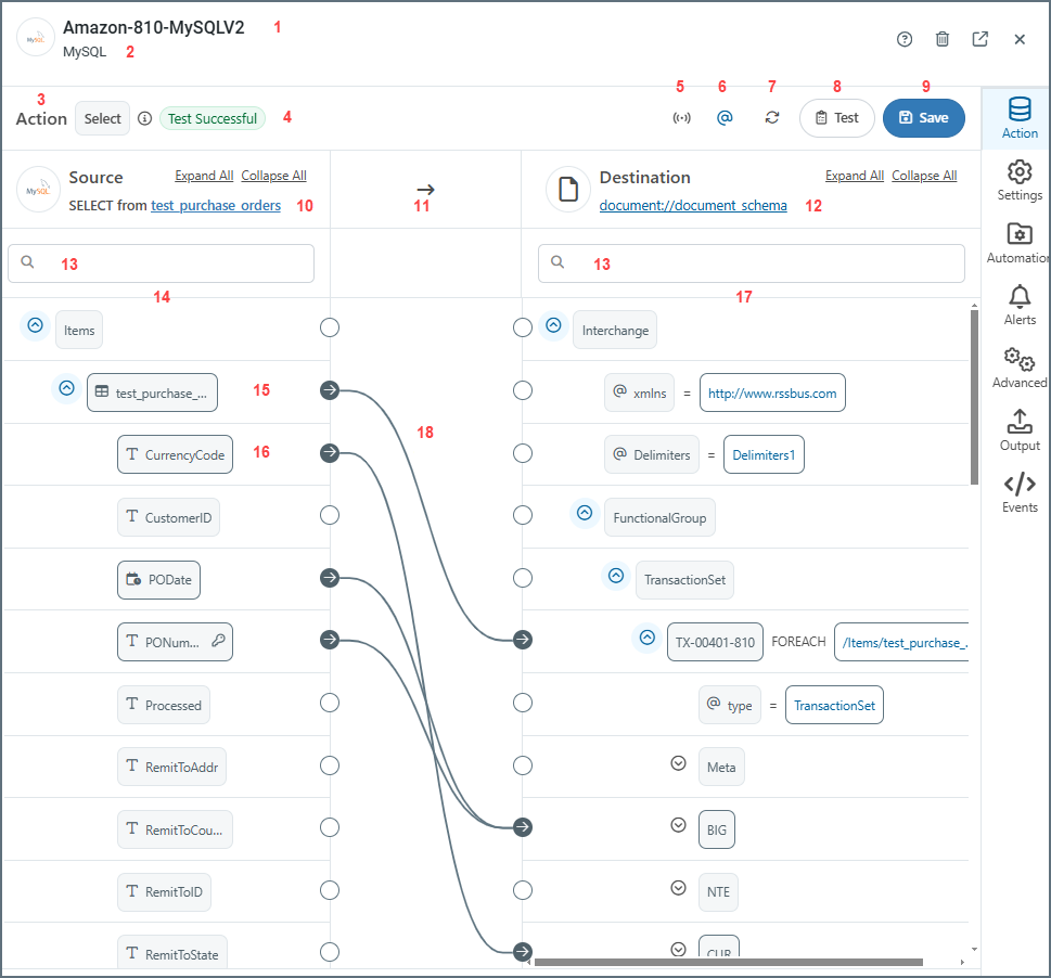
- The document name.
- The connector type.
- The action for the document. Values are Upsert for incoming documents, and Select for outgoing documents.
- Test status of the mapping. Values are Test Successful, Tested with Errors or Not Tested.
- Toggles XML streaming on or off. When on, the connector drops the Document Object Model (DOM) for the current iteration of the top-most
Foreachin the mapping after completing the loop. This can significantly improve performance for large XML documents. In situations where the connector cannot resolve the mapping, it automatically toggles XML streaming off. - Toggles whether to show or hide the XML attributes.
- Refreshes the mapping.
- Opens the Test Mapping page. The test result is shown in #4. (See Test Mapping for more information.)
- Saves the mapping.
- The target table in the configured data source.
- The direction of the mapping.
- The schema of the EDI document (an 810 invoice in this example).
- Search bars on the source and destination sides.
- Structure of the source table.
- The name of the table. This is also known as a table node.
- A column in the table. This is also known as a column node.
- The structure of the destination document.
- Completed mappings.
Understanding Source and Destination
Describe the source and destination content.
As mentioned previously, when you create an incoming document, you must specify the destination connector where the data will be sent. The EDI document structure is in the left pane and the connector table structure is in the right pane.
When you create an outgoing document, you must specify the source connector to pull the data from. Here, the connector table structure is in the left pane and the EDI document structure is in the right pane.
Arc provides a number of ways in which you can manipulate the information in the table and document structures. See Table Structure Nodes and Document Nodes for details.
To change the document schema, or to upload a template file that represents the source or destination XML structure, click the link to the document schema and choose Upload File. This is helpful if your partner provides you with a sample document of what they are expecting to send and/or receive. For example, if your partner provides you with a sample X12 850, you can convert it into XML by running it through an X12 connector in X12 to XML mode in a regular workspace. Then you can upload the output XML as a template file.

Browse to the template file, then click Upload Template File.
Actions
Two actions are available when you configure a connector:
- Upsert is the action for incoming documents. This action inserts or updates data into the target destination table. If a record already exists in the destination table, an update is performed on the existing data using the values provided from the input.
- Select is the action for outgoing documents. This action retrieves data from the target data source.
Table Structure Nodes
This topic describes the options available in the mapping pane that displays the source or destination table structure. There are two types of nodes in the structure: table nodes and column nodes. Table nodes represent the table itself and column nodes represent the columns in the table.
Table Nodes
Table nodes are indicated with a table icon. When you hover over a table node, you have two additional options:
-
Click the funnel icon to open the Add Mapping Conditions page which enables you to add filter conditions to the mapping. See Using the Condition Editor for more information. (Only available for incoming document mappings.)
-
Click the ellipses to open a list of options for that table node:
- Rename Table lets you change the name of the node.
- Remove Table removes the node.
- Table Settings opens an edit window that lets you select which columns to include in the mapping, and whether to apply filters. (Only available for outgoing document mappings.)
- Edit Columns opens an edit window that lets you select which columns to include in the mapping. (Only available for incoming document mappings.)
- Add opens a new list of nodes that you can create and use in your mappings. (Only available for incoming document mappings.) The options are:
- Add Header creates a header node that you can map a value to. The mapped value is not included in the output file but is added as a header on the mapping output message.
- Add Loop creates a loop node above the selected node and that node becomes nested within the loop node. See Loops for more information.
- Add Condition lets you add conditions to destination nodes so that data is only upserted to the destination if the condition is true. See Using the Condition Editor for details.
- Add Code Script opens the Add Script window where you can name the script and supply custom ArcScript.
- Add Variable creates a variable node below the selected node. See Variables for more information.
Column Nodes
Column nodes represent columns in a table. Every column node has a type, which is the column’s datatype in the database. There are seven different datatypes, each one with its own symbol. Hover over a column to see its datatype, size, and whether it is nullable. The datatypes are:
- String
- Number
- Binary
- Boolean
- Date
- Time
- Date and Time
Hover over a column row and click the ellipses to open a list of options for that node:
- Rename Column lets you change the name of the node.
- Remove Column removes the node.
- Add opens a new list of nodes that you can create and use in your mappings. (Only available for incoming document mappings.) The options are:
- Add Header creates a header node that you can map a value to. The mapped value is not included in the output file but is added as a header on the mapping output message.
- Add Loop creates a loop node above the selected node and that node becomes nested within the loop node. See Loops for more information.
- Add Code Script opens the Add Script window where you can name the script and supply custom ArcScript.
- Add Variable creates a variable node below the selected node. See Variables for more information.
- Add Tracking adds tracked headers to the mapping. When a node has tracking enabled, it displays a compass icon.
Document Nodes
Document nodes refer to the nodes on other side of the mapping: the non database side. These nodes are not explicitly related to a data source (a table with columns) but rather represent the EDI data in an XML structure. These nodes are mapped to for outgoing documents and mapped from for incoming documents.
For outgoing documents (using the Select action), click the funnel icon to open the Add Mapping Conditions page which enables you to add filter conditions to the mapping. See Using the Condition Editor for more information. Click the ellipses to use the following options in the destination document:
- Rename Node lets you change the name of the node.
- Edit XPath lets you edit the node XPath (only on elements already mapped as
Foreach) - Delete Node lets you delete the node from the document.
- Add Node
- Add Sibling adds a node at the same level as the selected node.
- Add Attribute adds an attribute to the selected node.
- Add Child adds a node as a child of the selected node.
- Add Header creates a header node that you can map a value to. The mapped value is not included in the output file but is added as a header on the mapping output message.
- Add Loop creates a loop node above the selected node and that node becomes nested within the loop node. See Loops for more information.
- Add Condition opens the Condition Editor where you can add conditions so that data is only upserted to the destination if the condition is true.
- Add Code Script opens the Add Script window where you can name the script and supply custom ArcScript.
- Add Variable creates a variable node below the selected node. See Variables for more information.
- Cut Node cuts the selected node from its current location.
- Copy Node copies the selected node.
- Paste as Child pastes the cut or copied node as a child of the selected node.
For incoming documents (using the Upsert action), click the ellipses in the source document structure to use the following options:
- Rename Node lets you change the name of the node.
- Delete Node lets you delete the node from the document.
- Add Node
- Add Sibling adds a node at the same level as the selected node.
- Add Attribute adds an attribute to the selected node.
- Add Child adds a node as a child of the selected node.
- Cut Node cuts the selected node from its current location.
- Copy Node copies the selected node.
- Paste as Child pastes the cut or copied node as a child of the selected node.
You can also use Edit Node to open the Edit Node Value page. See Using the Node Value Editor.
Loops
Creating a table node mapping establishes a Foreach relationship between the source and destination nodes. This means that each occurrence of the source element produces a corresponding destination element, including all of the destination element’s columns. Creating a column node mapping instructs the connector to populate the destination element with the value from the source element.
Map table node Foreach loops before column node Foreach loops. Establishing the loop relationships requires an understanding of the source and destination structures: whenever a repeated element in the source should result in a repeated element in the destination, those elements should be mapped together in a Foreach relationship.
Test Mapping
Once you have configured the mapping, you should test it. Click the Test Mapping button at the top of the page. The following image shows testing an incoming document.
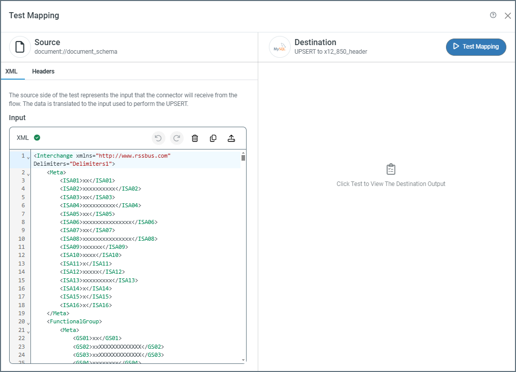
The source side of the test page has two tabs: XML and Headers (the Headers tab is only available on incoming documents). The source is populated with the XML representation of the document or table structure to test, but you can edit it as necessary. For incoming documents, click the Headers tab to add any headers you want to use in the mapping (see Tracked Headers for more information). When you are ready, click Test Mapping.
Test result indicators appear on the partner Workflow page and on the mapping itself. The values on the mapping are Test Successful, Tested with Errors or Not Tested. The Workflow page shows a check for successful tests, a brown exclamation mark for untested mappings, and a red exclamation for tests with errors. Hover over the icons for details about the errors.
Note: When you test incoming documents, you are testing with live data. When you click Test Mapping, Arc tries to perform the upsert after it tests the mapping.
Using the Node Value Editor
The Node Value Editor supports modifying values as they are mapped from the source to the destination. This editor uses the ArcScript language to format and dynamically generate content. To open the editor, hover over a node in the destination document and click the tablet and pencil ![]() icon.
icon.
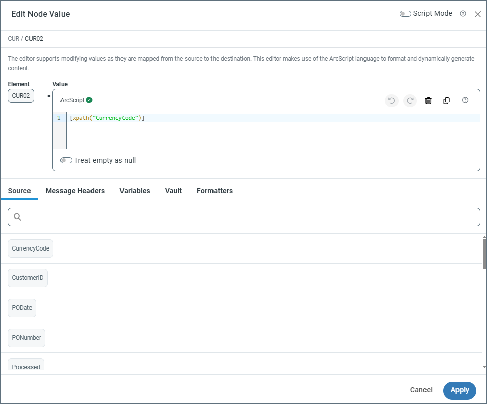
The editor contains a panel with the ArcScript expression used to render the result. When you edit a node that has already been mapped to an element from the source XML, the expression displays the xpath representing this mapping. From here, edit the expression to manipulate the value, or include references to additional nodes in the source XML.
Note: The editor validates your expression as you type. If you see an Invalid Expression message, you have some sort of syntax issue. This is typically caused by not escaping reserved characters such as square brackets, parentheses, or slashes.
Treat Empty As Null
Check Treat empty as null to treat empty input values (such as a string with a length of 0) as NULL output values. This is unchecked by default, so empty input values are treated as an empty string: “”
Leaving this setting unchecked can be useful in situations where mappings might interface with a database table that includes columns that do not accept NULL values. In this case, empty string values can prevent errors while inserting to the database, or empty string values pulled from the database might need to be converted to NULL to better reflect the dataset.
Source
Any expression in square brackets is evaluated as a variable in ArcScript. In most situations, variable expressions include an xpath() evaluation of an element in the source document. You can use multiple bracketed expressions to express multiple variables, either back-to-back or interspersed with literal characters (outside of square brackets).
For example, to combine the values at two different paths:
<Customer>
<First>Bruce</First>
<Last>Wayne</Last>
</Customer>
A single expression can join the two values:
[xpath('Customer/First')] [xpath('Customer/Last')]
Message Headers
Message headers help Arc track the progress of data through flows. You can add nodes as headers by clicking the ellipses on a node in the mapping and choosing Add Tracking. Once you have done that, the tracked field appears on the Message Header tab and you can reference it in your expression.
You can also include other message headers in your expression by using the Add Message Header field and providing the name of an existing header.

See Tracked Headers for details.
Variables
It can be useful to set variables at one point in the mapping and reference those variables again later in the mapping. The scope of a variable encompasses an entire document processed by the mapping. In other words, any attributes of the variable persist throughout the mapping and are only cleared when Arc finishes processing a file.
For example, a mapping might require tallying up the total cost of multiple line items in a purchase order (perhaps the mapping includes some number of LineItemCost elements and also a TotalCost element). You could add a variable to LineItemCost to sum the values of each LineItemCost element. If you include this variable in an element in the Foreach loop that loops over all of the line items, the sum would be the TotalCost when the Foreach loop exits.
To add a variable, click the ellipses on a node in the mapping editor and choose Add > Add Variable. Once you have done that, the variable appears on the Variables tab and you can reference it in your expression.
Vault
Use the Vault tab to add items from your Global Settings Vault to an expression. This is useful if you have values that you reuse in different places throughout a flow. You can define those values in the vault, then reference them at the beginning of the expression. Keep in mind that if you want the mapping to use the value of the item in the vault, you need to reference it inside square brackets; otherwise the editor interprets the item name as a literal.
Formatters
Formatters support manipulating the values returned at different xpaths. Formatters are separated by a pipe character (|) in the expression, and evaluated from left to right. For example:
[xpath('City') | toupper | substring(0,3)]
In this example, before the value of the City xpath is returned, all string characters are converted to upper case characters, and a substring of the first three characters is returned in the result. For example, if the source document had a value of:
<City>Durham</City>
The resulting expression returns the following:
DUR
The formatters are listed on the Formatters tab. Add a formatter to the expression by clicking it in the list.
String Manipulation
String manipulation is a common use case for the editor. Common string formatters include:
For example, you might want to split a CustomerName value from the input XML into two separate fields in the output XML. Use the split formatter to accomplish this. The parameters for split are the character around which to split the string and the index of the resulting array that should be returned (indexes begin at 1):
[xpath(CustomerName) | split(' ', 1)]
Find the full list of string formatters here.
Date Manipulation
Another common use case involves reformatting dates from the source document to the destination. This is supported by the todate formatter, which allows three arguments:
- output date format (mandatory)
- input date format (optional): Use this if the formatter cannot auto-detect the input datetime format.
- strict input format (optional): Use this to check whether the incoming date value matches the input format. If it does not, the task throws an error instead of converting the date to a standard date format. The default is not to check. To force the check, add
trueto the formatter.
The following example converts a date in the form of 12/21/22 to a date in the form of Friday, 21 December, 2022, and checks that the date value matches the input format:
[xpath(PurchaseDate) | todate(D, "mm/dd/yy", true)]
Additional functions that are useful for date calculation are dateadd and compare, which you can use to add or subtract fixed periods of time to a date, and to perform date comparisons.
Find the full list of date formatters here.
Number Operations
Number operations are useful for performing calculations on numerical values from the source XML. The following example converts cents to dollars, and ensures that the resulting value is a decimal value with two positions:
[xpath(ItemCost) | divide(100) | decimal(2)]
You can use number formatters to calculate tax and add the tax value to a total. The following example includes a nested set of number formatter expressions: each expression is evaluated from left to right, and a nested expression is evaluated in its entirety before returning to the outer expression:
[xpath(Subtotal) | divide(100) | multiply([xpath(TaxPercent) | divide(100) | add(1)]) | decimal(2)]
Find the full list of number formatters here.
Lookahead
The xpath() formatter supports lookahead syntax to further specify which values from the source document should be mapped to the destination. Lookaheads can help target a specific value in the midst of repeated XML element structures.
For example, your input XML might have multiple line items, only one of which contains the desired value. Each line item has the same xpath, so lookahead syntax is required to retrieve the desired value from the values at the same xpath.
The following XML demonstrates this situation. Notice that the LineItem elements have a matching XML structure:
<LineItem>
  <ItemType>Goods</ItemType>
  <ItemName>Widgets</ItemName>
  <ItemAmount>20.00</ItemAmount>
</LineItem>
<LineItem>
  <ItemType>Tax</ItemType>
  <ItemName>Sales Tax</ItemName>
  <ItemAmount>1.38</ItemAmount>
</LineItem>
Imagine that the amount for the Tax line item (1.38) needs to be mapped to the destination document, but not the amount for the Goods item (20.00). Since both line items have the same XML structure, an xpath alone is not enough to specify the Sales Tax line item amount. As an illustration, the following expression uses the correct xpath but retrieves the Goods item amount instead of the Tax item amount (because the Goods item amount is the first value that satisfies the xpath):
[xpath(LineItem/ItemAmount)]
In order to specify the Tax line item, the expression needs to look into the LineItem element for the ItemType element, which identifies the line item as a Tax item. The LineItem element is the lookahead ‘parent’, and the ItemType element is the lookahead ‘target’.
Lookahead syntax is as follows: inside the xpath expression, add square brackets directly after the parent element of the lookahead. Inside the square brackets, provide the xpath to the target element of the lookahead and use an equals expression to check the target value (notice that the square brackets must be escaped with backslashes):
[xpath(LineItem\[ItemType='Tax'\]/ItemAmount)]
This translates to “find the value from LineItem/ItemAmount for the LineItem element where LineItem/ItemType is Tax. The expression would return the value 1.38.
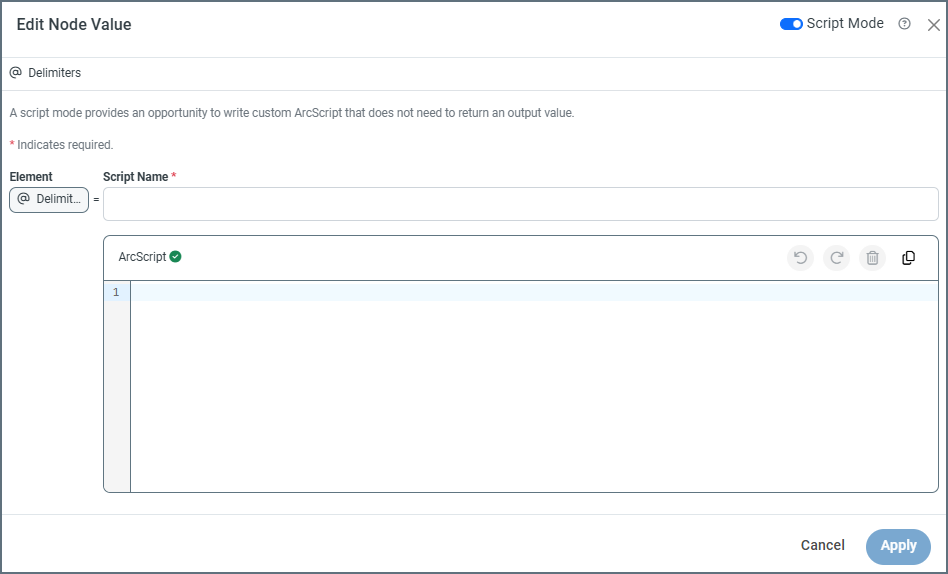
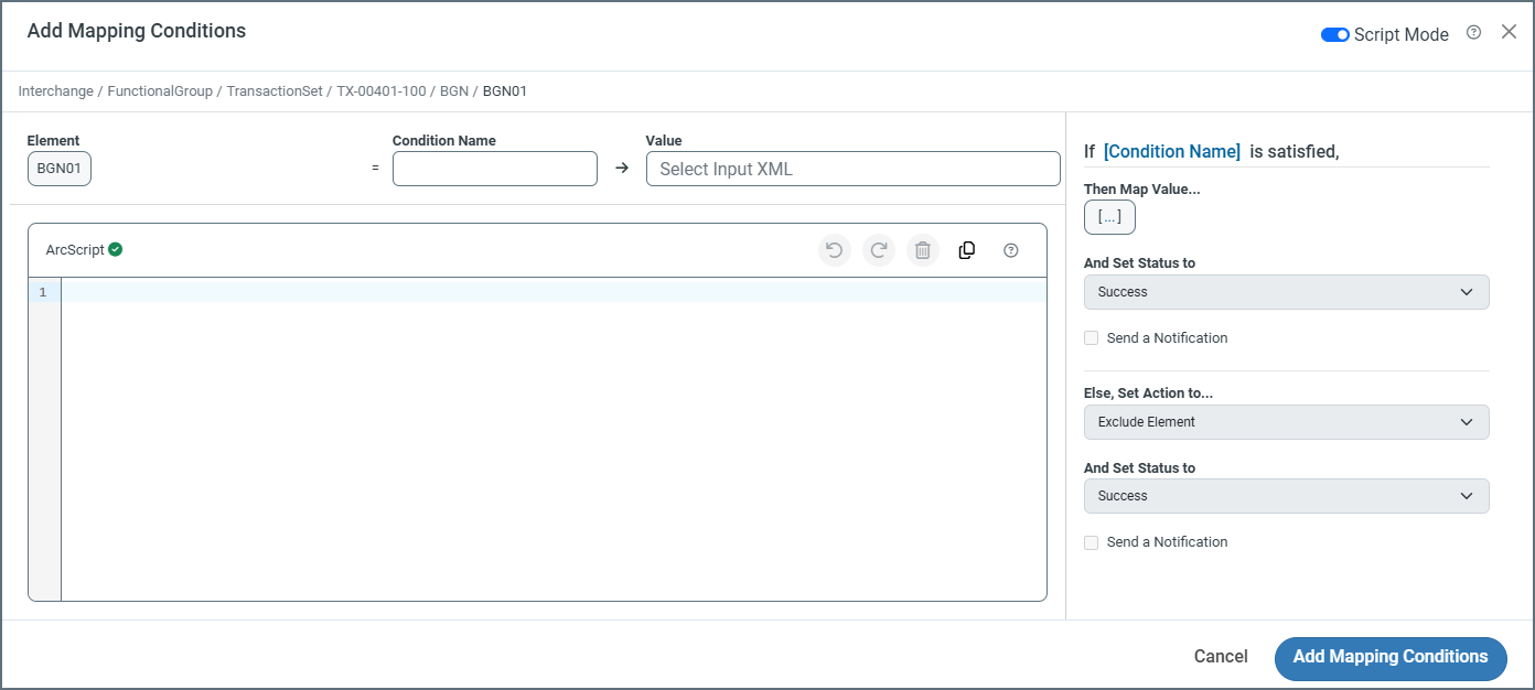
Script Mode
Use the Script Mode toggle at the top of the editor to switch the condition editor from designer mode to script mode. This means that conditions must be written in ArcScript, instead of using the standard designer mode. Script mode allows you to write custom ArcScript that does not need to return an output value. When script mode is enabled, it converts the node from a text node in the mapping to a script node, denoted by the open and close tags ![]() icon.
icon.
If you create an ArcScript condition that cannot be rendered in the designer, if you switch back to designer mode you are warned that Arc cannot render this configuration in designer mode. If you switch to the designer mode you lose all changes to the existing configuration.
Using the Condition Editor
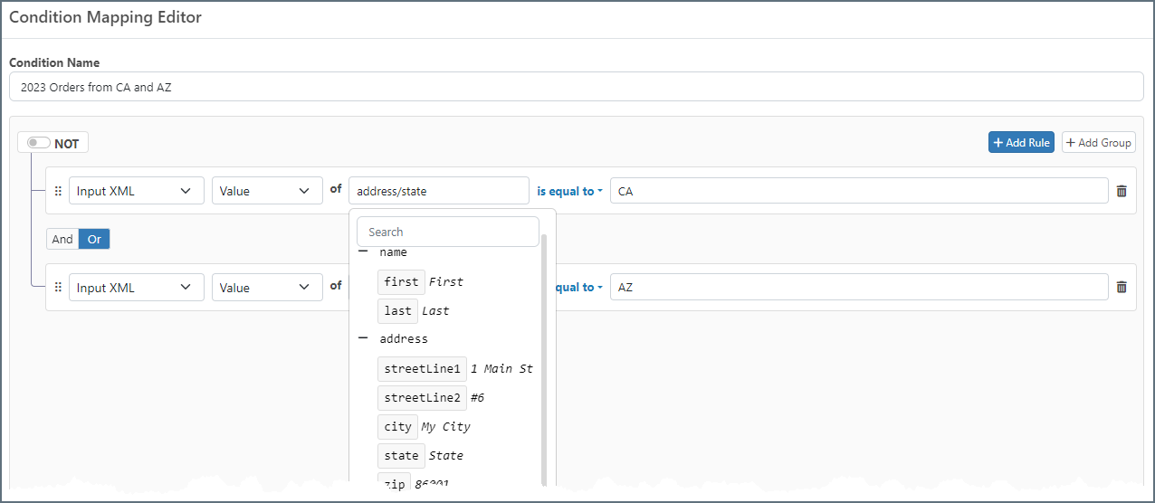
The Condition Mapping Editor supports adding conditions to destination nodes so that they are only included in the output document if the condition is true. You can build complex conditions by adding individual rules and/or groups of rules, then specifying what action the connector should take when the condition is satisfied.
To open the editor, hover over a node in the destination document and click the filter ![]() icon.
icon.
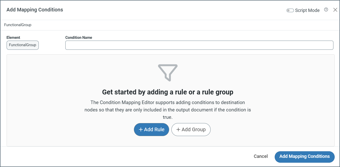
Give the condition a name, then click Add Rule or Add Group.
When you build your rules, use the dropdowns to make your selections. You can choose from the following:
- Input XML
- Value: The value at the XPath being evaluated
- Data Type: The data type of the value (String, Number, DateTime)
- Message Header
- Value: The value of the message header being evaluated
- Data Type: The data type of the value (String, Number, DateTime)
- Occurrences: The number of times the XPath occurs in the document
- Index: The index representing the current iteration of the Foreach loop that is being evaluated
- Variable
- Value: The value of the variable being evaluated
- Data Type: The data type of the value (String, Number, DateTime)
When you select an XPath for a condition, the editor displays a tree representation of the document so you can easily find the XPath you need, as shown in the image below.
You can reorder rules and groups. Click the handle  and drag the object to a new location.
When you have completed defining the condition, use the right side of the modal to specify what should happen when the condition is satisfied.
Choose a status of:
- Success
- Warning
- Error
Check Send a Notification and complete the To and Subject fields to send an email about the status of the condition.
Note: Click Configure Alerts to open a new browser tab where you can set the Email Settings on the Alerts tab of the Settings page. If these have not been configured correctly, email notification fails.
Finally, use the Else section of the modal to specify what should happen when the condition isn’t satisfied.
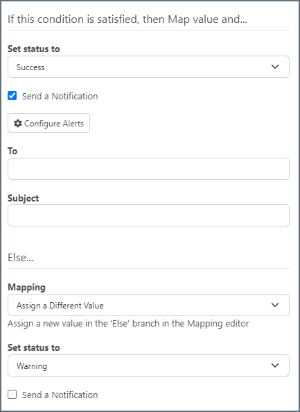
Use the Mapping dropdown to choose whether to:
- Exclude Element from the mapping altogether
- Map Value to map the value anyway
- Assign a Different Value to assign a different value (defined as an expression or custom script once you save the condition)
The status and notification options work in the same way as the top section.
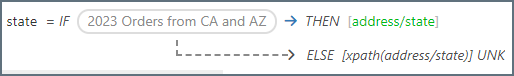
When you save the condition, it appears in the mapping editor and behaves in the same way as any other leaf node in the mapping. You can drag-and-drop an element from the source side, write expressions or custom scripts for it, etc.
Conditional logic can also be accomplished using lookahead syntax. Parent elements are often qualified by a child element that provides context to the values inside the parent. In these cases it might be easier to use lookahead syntax rather than create multiple conditions to exclude unwanted values. See Lookahead for more details on using lookahead syntax.
Custom Conditions
You can use ArcScript syntax to specify custom conditions. Click the Custom Script button to open the scripting window. When you have written your custom condition, use the right side of the page in the same way as described above to:
- Set the status of the message
- Send notifications
- Add Else conditions to your mapping, including excluding elements from the mapping if the condition is not met
Note: The editor validates your condition as you type. If you see an Invalid Condition message, you have some sort of syntax issue that must be resolved.
One common use of the custom condition editor is to compare two dynamic values from the source document (instead of comparing a single dynamic value against a static value).
For example, you could use the following custom condition to see whether two values in the source XML are equal:
'[xpath(element1)]' == '[xpath(data/element2)]'
Note: The single quotes in the example above are required.
You can also perform boolean logic in custom conditions by using ArcScript formatters, as in the following example:
[xpath(element1) | equals([xpath(data/element2])])]
Notice that this syntax does not require single quotes.
See Formatters for details on all of the ArcScript’s formatters.
Script Mode
Use the Script Mode toggle at the top of the editor to turn the the node into a script node. Script nodes allow you to write custom ArcScript that does not need to return an output value. When script mode is enabled, it converts the node from a text node in the mapping to a script node, denoted by the open and close tags ![]() icon.
icon.
Using Filters
If you need to filter the data that the connector selects in a source table structure, click the ellipses and choose Table Settings, then click the Filters tab. The Edit <TableName> Settings window opens, where you can define individual filters and filter groups.
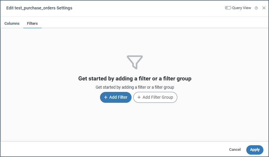
Creating a Filter Rule
To create a filter, follow these steps:
- Click Add Filter.
- In the drop-down list for the new rule, choose the column that you want to filter.
- Choose the filtering condition. The available filtering conditions depend on the data type for the column you select.
- If your filtering condition requires a value, enter that value in the blank value field. If your filtering condition does not require a value (for example, if you choose Is Null), the value field disappears.
For example, you could create a filter on a column named Author that only selects values that contain Smith. In this example, the column is Author, the condition is Contains, and the value is Smith.
Filter Groups
You can apply multiple filters to your table by clicking Add Filter. Filters are separated by groups, and all filters belong to the same group by default. You can create multiple groups to separate filters by clicking Add Group.
Each filter in a group interacts with the others based on the options you select at the top of the group:
- Use the NOT toggle to invert the filter conditions. For example, in the Author filter example above, enabling the NOT toggle instructs the connector to select Author values that do not contain Smith.
- Select AND or OR to determine the group logic for multiple filters.
- If you select AND, every filter in the group must be true for the filter conditions to be met.
- If you select OR, at least one filter in the group must be true for the filter conditions to be met. Multiple filter can be met, and the results are the same as if only one were met.
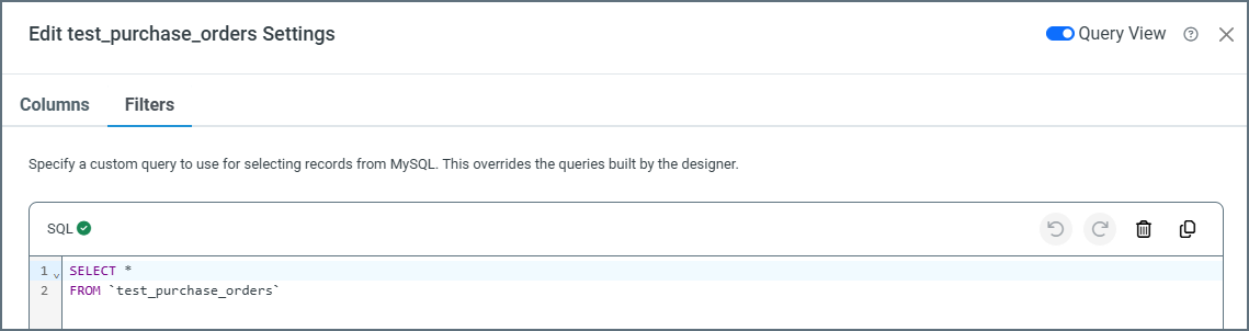
Using Query View
Toggle on Query View to write a custom SQL query that selects data from your data source. This overrides any queries created in the designer.