Designing a Flow
Version 22.0.8473
Version 22.0.8473
Designing a Flow
To manage the flow in CData Arc, navigate to the Flows selection in the Administration console to access the Flow Designer.
You will see a grid layout for the designer, and if you have any pre-existing connectors, a visual representation of those connectors on the grid. From here, you can add new connectors to the flow, connect and rearrange existing connectors in the flow, and configure existing connectors from the designer.
When viewing the designer, left-click on any empty space and hold to drag the designer into position for a better view.
In the lower-right corner of the designer, there is a slider where you can zoom in or out on the selected view or select the default home view of the designer.
Note: This zooming functionality is also available from the mouse if you have a scroll wheel feature.
Creating Connectors in the Flow
To add a new connector to the flow, select a Connector type from list on the left side of the designer.
Once you drag your selection onto the designer, you are prompted to name your new connector. Be sure to choose a name that briefly describes the operation that connector performs.
Connecting Connectors in the Flow
To rearrange and connect existing connectors in the designer, click on and drag any of your existing connectors to move them across the grid and rearrange them into the desired configuration.
To connect connectors, select the bright blue dot attached to the right side of a connector, and drag it to the gray dot on the left side of the connected connector, as shown in the following image:
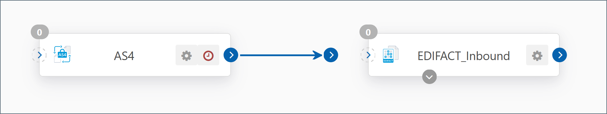
This creates a logical relationship between the two connectors so that once the first connector generates a message or file, it is passed directly to the connected connector for processing.
If you want to reconnect the connector to another connector, select the bright blue dot from the left side of the connected connector, and move it to an unconnected connector. If you want to disconnect the connector, drag the blue dot from the connected connector to any empty space on the designer.
Configuring Connectors in the Flow
To configure an existing connector from the designer, click the cogwheel next to the name of the connector to open the connector configuration wizard, as shown in the following image:
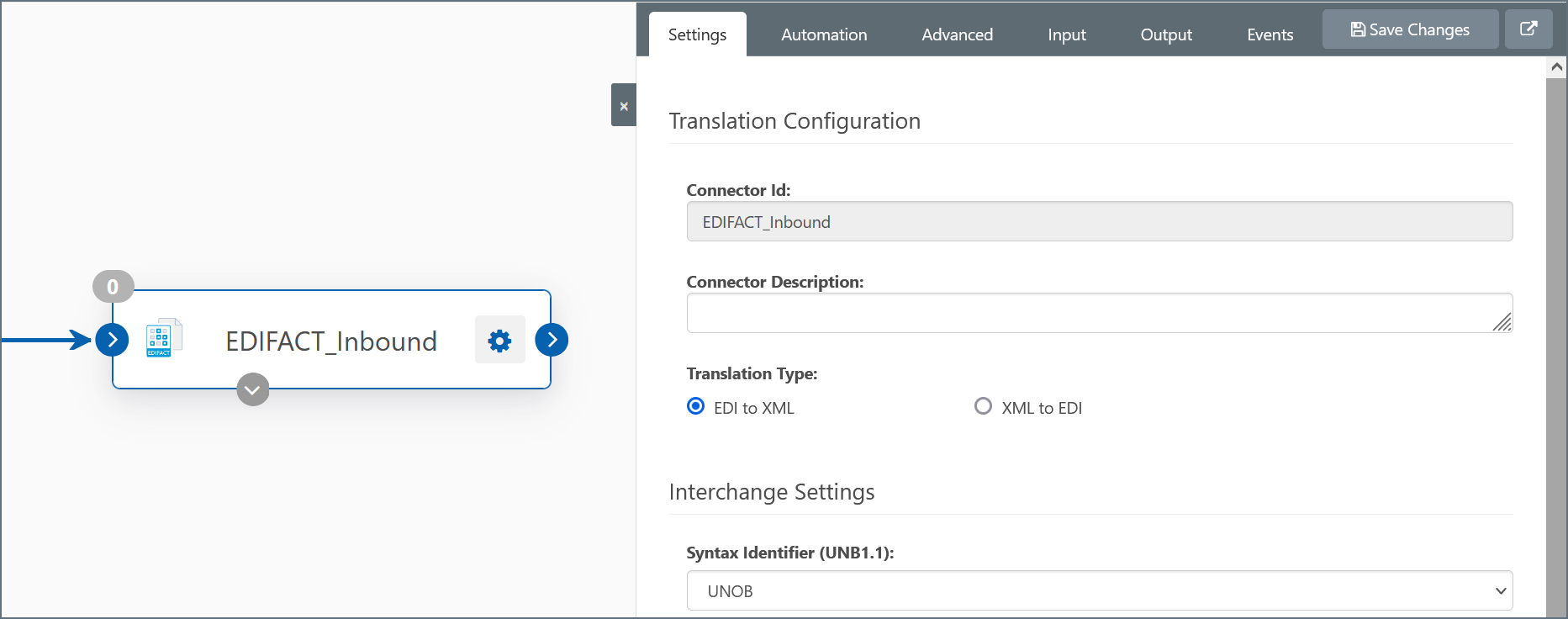
From this tab, you can configure settings for the connector from the Settings and optionally, Advanced tabs, and test the connector configuration from the Send tab.
When you have finished making changes to the connector configuration, you can select the square gray x on the left side of the panel to minimize the connector configuration wizard and return that space to the designer.
Mappings
Data Sources have input and output mappings that tell the connector how to process inbound data and how to format outbound data, respectively. You can configure the connector to lookup fields, update flags, and more when processing data.
Input mappings are used to process incoming messages into the data source.
- Click the plus sign icon to add input mappings.
- Edit, code, execute, or delete mappings by selecting the icons in the Mappings table.
Output mappings define what data will be exported on the receive polling interval specified in the automation section.
- Click the plus sign icon to add output mappings. Optionally, click Play to execute all templates or Reset to reset the list of processed rows.
- Edit, code, execute, or delete mappings by selecting the icons in the Mappings table.
Best Practices
Most Flows have a connector at which data enters the Flow and a connector at which data exits the Flow. For some cyclical Flows, the entry and exit point may be the same connector.
For example, data may enter the Flow at an AS2 Connector when an external trading partner sends a business document over AS2. The data from this business document may need to be imported into a back-end system like a database. In this case, the AS2 Connector and the Database Connector are the entry and exit points for the Flow.
When creating a new Flow, it is often easiest to start with these entry and exit connectors. Then, “work inwards” by adding more connectors to the Flow that fill in the steps between the entry and exit point (e.g. add connectors that transform an inbound AS2 payload into a database insert).
Interacting with the Local File System
CData recommends using the File connector when configuring a Flow that interacts with the local file system. This is especially important for folders that are shared with external monitoring processes. Guidelines for file pickup and file drop-off are outlined below.
File Pickup
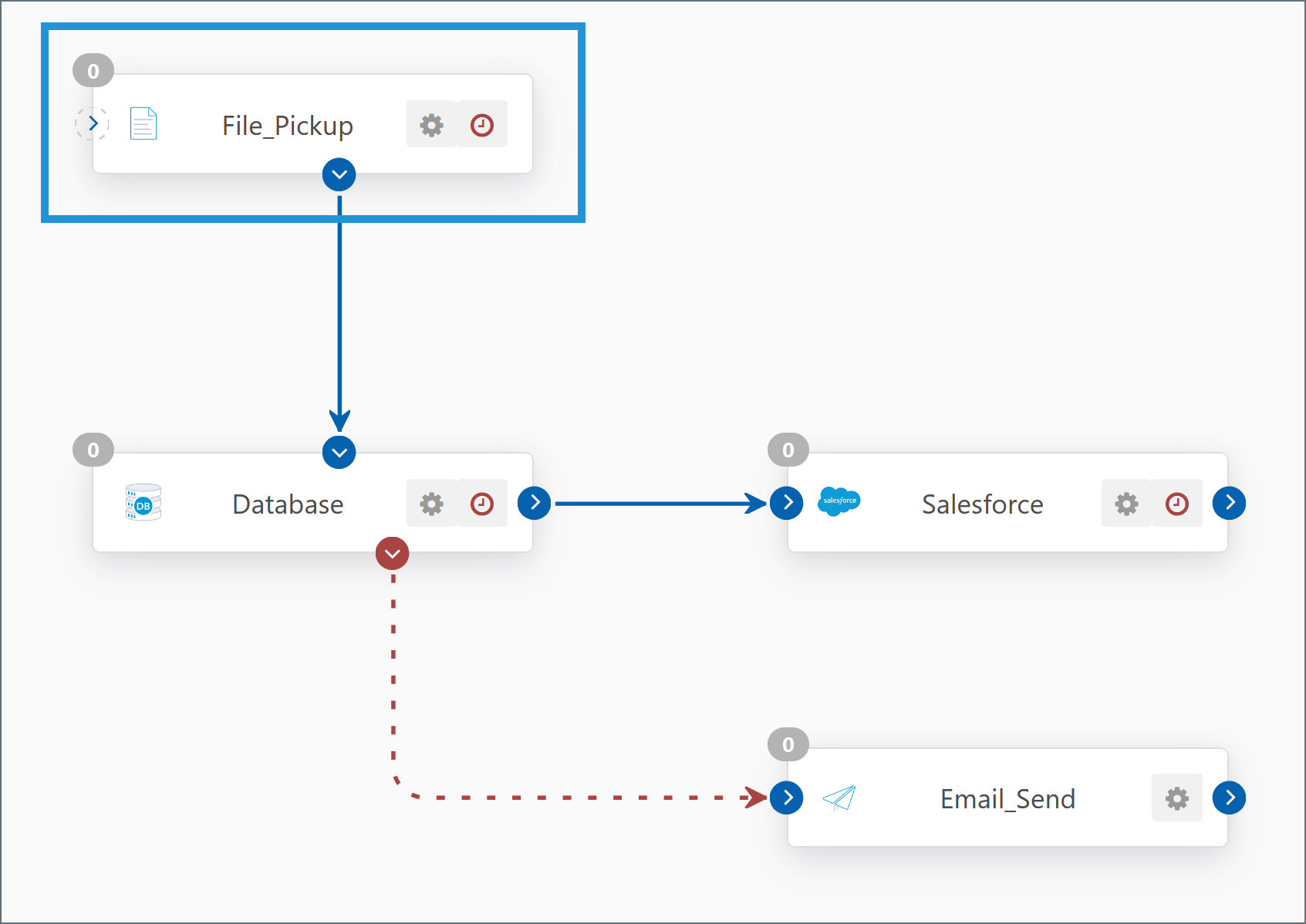
To monitor a directory for files that will be processed in Arc, add a File connector at the beginning of your Flow as shown below:
Configure the connector according to these steps:
-
Open the Settings tab for the connector.
-
Set the Path property of the connector to the directory that you want to monitor.
-
Configure the File Mask property with the file pattern that you want to perform a listing for.
-
To avoid reprocessing files that have already been picked up, configure one of these two options according to what works best for your Flow:
- In the Receive section, check the box for Delete files (after received). This option deletes files after they have been processed.
- Alternatively, under Caching, check one or both caching options to maintain file size and/or timestamp record of files that have been processed. The application skips cached files but does not delete them.
-
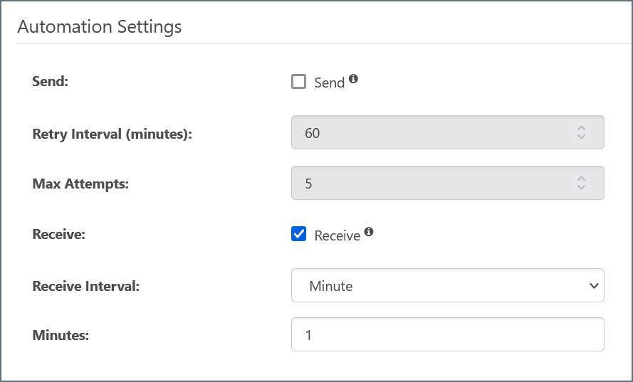
Open the Automation tab.
-
Disable Send automation.
-
Enable the Receive automation and set the desired polling interval for the directory.
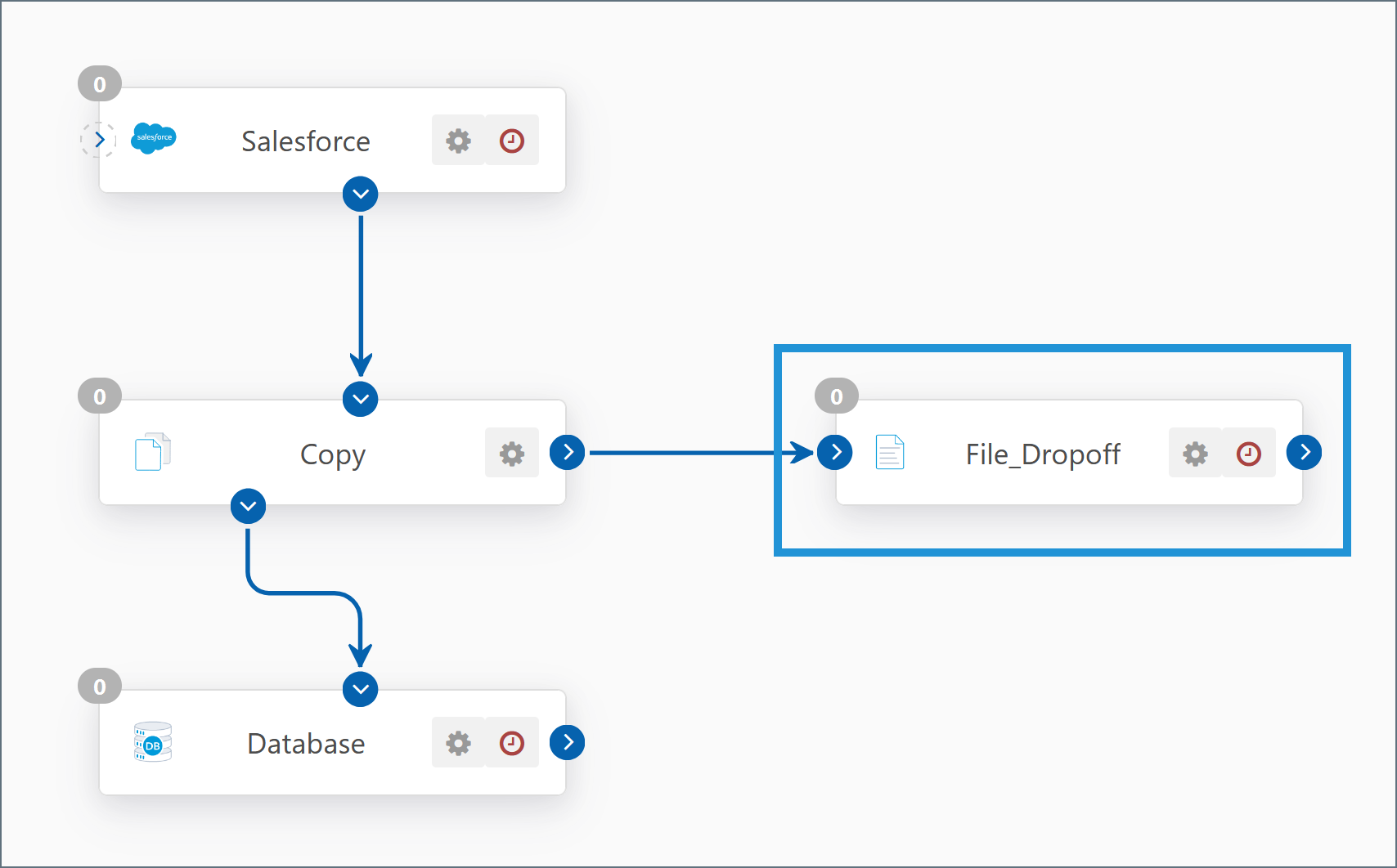
File Drop-Off
To drop off processed files to the local file system, add a File connector to the end of your Flow as shown below:
Configure the connector according to these steps:
-
Open the Settings tab for the connector.
-
Set the Path field to the directory where you want to drop off files. You can use macros to dynamically resolve paths based on date and time; highlight the Path field in the connector settings for more information.
-
Open the Advanced tab.
-
Set the desired Overwrite Option to handle files that already exist in the destination path.
File Transfer Connectors are Partner-Specific
Connectors that send or receive files over the network (e.g. AS2, AS4, FTP, SFTP, OFTP, etc) are bi-directional, but are configured for a single trading partner (i.e. a single remote party). In other words, a single AS2 Connector could both send and receive AS2 messages with Amazon, but it could not also send or receive files with Walmart.
Many MFT (Managed File Transfer) connectors require setting up a Profile to exchange files. The Profile page contains a tab for configuring application-wide settings for each supported protocol. For example, the information configured in the AS2 Profile is used in all AS2 Connectors, and partner-specific AS2 connection details are configured within each AS2 Connector.
Use a Naming Convention for Connectors
Connectors should always be given a descriptive name that communicates the role of the connector within the Flow.
- The name of a Managed File Transfer connector (e.g. AS2, AS4, FTP, SFTP, OFTP, etc) should indicate the remote party with whom files will be exchanged, and the protocol over which the exchange will occur. For example: Walmart_Production_AS2
- The name of an EDI connector (e.g. X12 and EDIFACT) should indicate the name of the partner with whom the EDI document is exchanged, the direction of translation, and the format of the document. For example: Walmart_X12_Outbound
- The name of a Data Mapping connector (e.g. XML Map) should indicate the format/schemas that the connector is mapping from and mapping to. For example: Map_850_to_Orders
- The name of a Back-End Integration connector (e.g. Database, MySQL, CData) should indicate the specific back-end system and the table within that back-end system (if applicable). For example: PostgreSQL_Orders_table
Use XML for Data Transformation
Arc uses XML as an intermediary format for data manipulation and transformation. Many connectors translate files of various formats into XML and vice versa (e.g. the X12 Connector, EDIFACT Connector, CSV Connector etc). Additionally, Arc uses XML to model back-end system input and output (e.g. SELECTS and INSERTS into database-like systems).
Since most source and destination formats can be represented as XML, data transformation Flows often have the following structure:
- A connector that pulls or receives data in its original (source) format
- A connector that converts this source format into XML (if it is not already XML)
- An XML Map Connector that transforms this source XML into a new structure representing the target (destination) format
- A connector that converts this transformed XML into the destination format (if a non-XML format is required)
- A connector that sends the finalized file to its intended destination
The XML Map Connector is the engine that performs the critical work in these data transformation Flows. Becoming comfortable with data transformation is often a matter of familiarizing oneself with the XML Map Connector’s visual designer.
Organize Flows into Workspaces
Multiple separate Flows can be configured within the same Flows canvas without risk of cross-contamination, but dividing Flows into different Workspaces can help reduce clutter and maintain organization.
The cogwheel in the top-right of the Flows page can be used to create new workspaces, import or export workspace configuration settings, and delete the current workspace (except for the Default workspace). Only the connectors from the current workspace are displayed at any given time.
Connectors in different workspaces cannot be connected to each other, and the data and configuration files specific to these connectors are held in separate folder structures.