X12 Connector
Version 24.1.8899
Version 24.1.8899
X12 Connector
X12 connectors support generating X12 files from XML and converting X12 files into XML.
Overview
When receiving X12 documents, X12 connectors validate X12 interchange headers and convert the X12 document into XML. This is useful as a staging step, because XML is the primary format that CData Arc uses to manipulate data in a flow. The X12 connector automatically reads the input file to determine the appropriate X12 schema, then parses the document according to this schema.
When generating X12 documents, X12 connectors convert XML into X12 document syntax and apply the appropriate X12 interchange headers. This is useful as the final step for creating an X12 document, after the XML data has been fetched and transformed elsewhere in the flow.
Note: Interchange header validation can be avoided by selecting Test Data in the Usage Indicator connector setting.
An X12 connector can also automatically generate acknowledgments for incoming X12 documents. For more information, see Acknowledgments.
Connector Configuration
This section contains all of the configurable connector properties.
Settings Tab
Translation Configuration
Settings related to the core operation of the connector.
- コネクタId コネクタの静的な一意の識別子。
- コネクタの種類 コネクタ名とその機能の説明が表示されます。
- コネクタの説明 コネクタとフローにおけるロールについて自由形式の説明を記載するオプションのフィールド。
- Translation Type Whether the connector is converting an X12 document into XML, or XML data into an X12 document.
Interchange Settings
Settings related to the interchange headers of X12 documents. When generating documents, these settings are applied as interchange headers in the resulting document. When parsing documents, the interchange settings are used to validate the incoming document.
- Sender Id Qualifier (ISA05) Qualifies the Sender Identifier by providing context to the value.
- Sender Identifier (ISA06) Identifies the sending party in the X12 communication (when generating an X12 document, this should be your identifier).
- Receiver Id Qualifier (ISA07) Qualifies the Receiver Identifier by providing context to the value.
- Receiver Identifier (ISA08) Identifies the receiving party in the X12 communication (when generating an X12 document, this should be your partner’s identifier).
- Control Version Number (ISA12) Identifies the control version for the interchange.
- Usage Indicator (ISA15) Whether the data exchanged represents test data, production data, or general information. When this is set to Test Data, interchange headers are not validated.
- Functional Group Check this to automatically add the sender and receiver identifiers to the Functional Group Settings on the Advanced tab.
Acknowledgments
Settings related to generating and requesting acknowledgments.
- TA1 Acknowledgment Whether to send TA1 interchange acknowledgments.
- Functional ACK Whether a functional ACK should be returned (when receiving) and requested (when sending). A functional acknowledgment serves as an indication of acceptance or rejection of the received interchange and transaction set.
- Functional ACK Type Check this to specify whether to use a 997 or 999 functional acknowledgment.
Automation Tab
Automation Settings
Settings related to the automatic processing of files by the connector.
- Send A toggle that instructs the connector to automatically send files when they are ready.
- Resend Interval The interval the connector waits before resending a file that received a negative ACK. For example, if a trading partner receives the file but something is wrong with it and they send back a negative ACK, this setting specifies how long to wait before sending the file again.
- Max Attempts (async) The maximum number of times the connector processes the input file when a functional ACK is requested. Success is based on the return of a functional ACK within the Resend Interval. If a successful functional ACK is not returned, the connector resends the file until Max Attempts is reached. If this is set to 0, the connector resends the file indefinitely.
Performance
コネクタへのリソースの割り当てに関する設定。
- 最大ワーカー数 このコネクタでファイルを処理するためにスレッドプールで消費されるワーカースレッドの最大数。設定された場合、これは設定 > オートメーションページのデフォルト設定をオーバーライドします。
- 最大ファイル数 コネクタに割り当てられた各スレッドが送信するファイルの最大数。設定された場合、これは設定 > オートメーションページのデフォルト設定をオーバーライドします。
アラートタブ
アラートとサービスレベル(SLA)の設定に関連する設定。
コネクタのE メール設定
サービスレベル(SLA)を実行する前に、通知用のE メールアラートを設定する必要があります。アラートを設定をクリックすると、新しいブラウザウィンドウで設定ページが開き、システム全体のアラートを設定することができます。詳しくは、アラートを参照してください。
サービスレベル(SLA)の設定
サービスレベルでは、フロー内のコネクタが送受信すると予想される処理量を設定し、その量が満たされると予想される時間枠を設定できます。CData Arc は、サービスレベルが満たされていない場合にユーザーに警告するE メールを送信し、SLA を At Risk(危険) としてマークします。これは、サービスレベルがすぐに満たされない場合に Violated(違反) としてマークされることを意味します。これにより、ユーザーはサービスレベルが満たされていない理由を特定し、適切な措置を講じることができます。At Risk の期間内にサービスレベルが満たされなかった場合、SLA はViolated としてマークされ、ユーザーに再度通知されます。
サービスレベルを定義するには、予想処理量の条件を追加をクリックします。
- コネクタに個別の送信アクションと受信アクションがある場合は、ラジオボタンを使用してSLA に関連する方向を指定します。
- 検知基準(最小)を、処理が予想されるトランザクションの最小値(量)に設定し、毎フィールドを使用して期間を指定します。
- デフォルトでは、SLA は毎日有効です。これを変更するには、毎日のチェックをOFF にし、希望する曜日のチェックをON にします。
- 期間終了前にステータスを’At Risk’ に設定するタイミングを使用して、SLA がAt Risk としてマークされるようにします。
- デフォルトでは、通知はSLA が違反のステータスになるまで送信されません。これを変更するには、‘At Risk’ 通知を送信のチェックをON にします。
次の例は、月曜日から金曜日まで毎日1000ファイルを受信すると予想されるコネクタに対して構成されたSLA を示しています。1000ファイルが受信されていない場合、期間終了の1時間前にAt Risk 通知が送信されます。

Advanced Tab
EDI Delimiters
Settings that specify which characters separate elements, segments, and so on.
- Data Element Separator The character that separates individual data elements in the document.
- Component Element Separator The character that separates elements within a composite data structure in the document.
- Segment Terminator The character that indicates the end of a segment in the document.
- Suffix Appended to the Segment Terminator to distinguish segments.
Interchange Settings
Additional settings related to the X12 interchange headers.
- Authorization Qualifier (ISA01) Qualifies the Authorization Id setting by providing context for the value.
- Authorization Id (ISA02) Identifies the authorization level associated with the interchange.
- Security Qualifier (ISA03) Qualifies the Security Password setting by providing context for the value.
- Security Password (ISA04) Represents security information about the interchange.
- Control Standards Identifier (ISA11) Identifies the X12 standard. The only valid value is U.
Functional Group Settings
Settings related to the functional group headers of X12 documents. These optional identifiers can help group similar interchanges or facilitate sub-addressing in an organization.
- Sender Identifier (GS02) Identifies the sending party in the X12 communication.
- Receiver Identifier (GS03) Identifies the receiving party in the X12 communication.
- Date Format (GS04) How the datestamp should be formatted.
- Time Format (GS05) How the timestamp should be formatted.
- Responsible Agency Code (GS07) Identifies the issuer of the X12 standard.
- Identifier Code (GS08) Identifies the version, release, and industry of the X12 standard.
Advanced Settings
Settings not included in the previous categories.
- Batch Transactions An interchange can contain multiple transactions. When this is not checked, the connector creates a separate output file for each transaction in the interchange. When checked, the connector groups all transactions into a single output file. Only applicable when the Translation Type is X12 to XML.
- Use Reference Id When checked, when you are translating X12 into XML, reference Ids are used to name XML elements. Only applicable when the Translation Type is X12 to XML. For example:
<_143>value</_143>
If this is unchecked, the Reference designator is used to name XML elements:<BEG03>value</BEG03> - Encoding Specifies the character encoding (such as ASCII or UTF-8).
- Expand Qualifier Values When checked, XML elements containing an EDI qualifier include child elements containing the qualifier code and value. For example:
<N101>
<Code>ST</Code>
<Value>Ship To</Value>
</N101> - Functional Acks By default, all functional acknowledgments (997, 999) are routed to the connector selected in the flow diagram, and XML translations are not received in the Output tab. Check this to have the translated acknowledgment also be included in the Output tab. This allows functional acknowledgments to be integrated into a destination source in addition to new EDI documents.
- Generate Description As When translating X12 into XML, descriptions of the X12 segments and elements can be provided as context for the X12 data. Use this dropdown to choose whether to add this context as an XML comment or as XML attributes.
- HIPAA Schemas When checked, the connector uses a separate set of EDI schemas with HIPAA constraints applied when translating and validating documents. This setting is ignored for EDI documents other than healthcare documents subject to HIPAA.
- HIPAA 278 Two separate schemas can be used for 278 documents, depending on whether these should be interpreted as requests or responses. When checked, the request schema is used; otherwise the response schema is used.
- ローカルファイルスキーム コネクタがアウトプットするメッセージにファイル名を割り当てるスキーム。ファイル名にマクロを動的に使用して、識別子やタイムスタンプなどの情報を含めることができます。詳しくは、マクロ を参照してください。
- Nest Loops When checked, the connector detects EDI structures that have hierarchical relationships embedded in the EDI data, and generates XML with these hierarchical relationships represented as parent-child relationships. See Master-Detail Hierarchy: Translating HLLoops for more information.
- 処理の遅延 インプットフォルダに置かれたファイルの処理を遅延させる時間(秒)。これは旧式の設定です。代替として、ローカルファイルシステムの管理にはFile コネクタの使用がベストプラクティスです。
- SNIP Validation When enabled, the connector performs the first three levels of SNIP Validation for HIPAA compliance: (1) the syntactical integrity of the document, (2) the presence of required segments and appropriate repetitions for repeated segments, and (3) the correct mathematical relationship between claim line items and claim totals. Higher levels of SNIP Validation (4+) might require a Validate connector or custom script.
- Strict Schema Validation Whether the connector should Ignore, Warn, or Fail when the following are detected: repeat counts above the allowed number, missing required elements or segments, invalid qualifier and code values, disallowed element lengths, and invalid element values. Choosing Disable turns off the schema validation checks.
- Track ISA06 Whether to add ISA06 values as tracked headers to processed messages. These headers are required when running EDI Reports.
- Track ISA08 Whether to add ISA08 values as tracked headers to processed messages. These headers are required when running EDI Reports.
- Track Transaction Types Whether to add transaction types as tracked headers to processed messages. These headers are required when running EDI Reports.
- Validate Identifiers Check this to ensure that the identifiers in the translated document match the identifiers in the connector’s configuration.
Message
- Sent フォルダに保存 チェックすると、コネクタで処理されたファイルをコネクタのSent フォルダにコピーします。
- Sent フォルダのスキーム 選択された時間間隔に従ってSent フォルダ内のメッセージをグループ化するようコネクタに指示します。例えば、Weekly オプションを選択すると、コネクタは毎週新しいサブフォルダを作成してその週のすべてのメッセージをそのフォルダに格納します。ブランクに設定すると、コネクタはすべてのメッセージをSent フォルダに直接保存します。多くのメッセージを処理するコネクタの場合、サブフォルダを使用するとメッセージが整理されてパフォーマンスが向上します。
Logging
- Log Level The verbosity of logs generated by the connector. When you request support, set this to Debug.
- Log Subfolder Scheme Instructs the connector to group files in the Logs folder according to the selected interval. For example, the Weekly option instructs the connector to create a new subfolder each week and store all logs for the week in that folder. The blank setting tells the connector to save all logs directly in the Logs folder. For connectors that process many transactions, using subfolders helps keep logs organized and improves performance.
- Log Messages Check this to have the log entry for a processed file include a copy of the file itself. If you disable this, you might not be able to download a copy of the file from the Input or Output tabs.
Miscellaneous
Miscellaneous settings are for specific use cases.
- Other Settings Enables you to configure hidden connector settings in a semicolon-separated list (for example,
setting1=value1;setting2=value2). Normal connector use cases and functionality should not require the use of these settings.
Converting Formats
The following sections detail the process of converting X12 to XML and vice versa.
X12 to XML
Setting the Translation Type to X12 to XML instructs the connector to parse incoming X12 documents into XML. The connector first reads all of the header information for the Interchange and Functional Group sections of the document and validates them against the configured connector settings (unless Usage Indicator is set to Test Data). The connector then parses out the specific X12 schema used in the document and loads the schema from the x12_schemas folder on disk (additional schema files can be downloaded from our website for free). Using the schema, the connector generates XML representing the X12 structure of the document, populates the XML with the values from the document, and provides context to each value either as XML comments or as attributes in the XML elements (based on the value of Generate Descriptions As).
To see this process with a set of test X12 documents, navigate to the Input tab of an X12 connector (with Translation Type set to X12 to XML) and select More > Create Test Files. X12 documents for an invoice, purchase order, purchase order acknowledgment, and shipping notice are automatically generated and placed in the Input directory. After these test files are processed by the connector, navigate to the Output tab to see the resulting XML.
Once X12 documents are converted to XML, the data can be transformed and manipulated in many ways. Commonly, X12 data needs to be stored in a database or other back-end application system. Since Arc uses XML to represent inserts into these back-end systems, storing the X12 data becomes a matter of mapping one XML structure onto another. This is typically done with the visual designer-driven XML Map connector.
XML to X12
Setting the Translation Type to XML to X12 instructs the connector to generate an X12 document out of an XML representation of the document. After the connector has constructed the X12 message out of the data parsed from the XML, it adds functional group and interchange headers according to the configured connector settings.
To see this process with a set of test XML files, navigate to the Input tab of an X12 connector (with Translation Type set to XML to X12) and select More > Create Test Files. XML files representing an invoice, purchase order, purchase order acknowledgment, and shipping notice are automatically generated and placed in the Input directory. After these test files are processed by the connector, navigate to the Output tab to see the resulting X12 document.
X12 Acknowledgments
The following sections detail the three types of X12 acknowledgments (ACKs), and how Arc expects, processes, and generates ACKs.
Interchange ACKs, 997s, and 999s
A TA1 is the commonly accepted form of interchange acknowledgment. It is an indication that an interchange has taken place between the two parties, although not necessarily that any individual message has been exchanged. These serve as a receipt to the sender indicating that the EDI message was successfully received, but it does not specify whether there were any issues while processing the content of the message.
The 997 (Version 4010), 997 (Version 5010), or 999 acknowledgements are considered functional ACKs—acknowledgements that an individual message (such as an invoice or purchase order) has been accepted. These are generated in response to a bidirectional agreement by both parties.
Expecting, Processing, and Generating Acknowledgments
Expecting Acknowledgements
X12 connectors, while operating in XML to X12 mode, can be configured so that both interchange and functional acknowledgments can be requested for an interchange. When TA1 Acknowledgment or Functional ACK is checked in the Acknowledgments section of the Settings tab, the connector maintains a Pending ACK status for a transmission until the appropriate ACKs have been returned and processed. This means that the connector status can be used to determine whether the recipient has confirmed that they received the interchange.
The following diagram shows the logical flow involved when expecting an ACK from an invoice document:
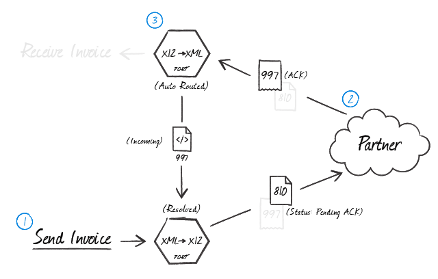
In the illustration above, an X12 connector operating in XML to X12 mode generates the document to be exchanged (1) and holds it in a Pending ACK state while the document is transmitted to the trading partner. The trading partner processes the transmission according to their business logic and creates acknowledgments in accordance with the configured exchange parameters (2). When the acknowledgments are returned, they are processed according to the information in the next section (3).
Processing Acknowledgments
In a typical flow, X12 ACKs arrive at an X12 connector operating in X12 to XML mode. This X12 connector can be configured to automatically route any received acknowledgments to the X12 connector that originally generated the document being acknowledged. Routing ACKs between X12 connectors is configured visually on the Flows canvas by dragging the gray dot at the bottom of the X12 connector in X12 to XML mode onto the X12 connector that is in XML to X12 mode.
Once the X12 connector in XML to X12 mode receives the routed ACK, it pairs the ACK to the original message and changes its state from Pending ACK to Sent.
Generating Acknowledgements
When an X12 connector in X12 to XML mode receives a message and generates the corresponding XML, it can automatically generate acknowledgments for the received message. To accomplish this, check TA1 Acknowledgment and/or Functional ACK expected in the Acknowledgments section of the Settings tab. These acknowledgments must be routed to another X12 connector (in XML to X12 mode) to finalize the ACK. The connector to which the ACK is routed applies interchange headings and passes the ACK along to the next connector in the flow like any other X12 message. To route the ACK appropriately, drag the gray dot at the bottom of edge of the X12 connector in X12 to XML mode onto the X12 connector that is in XML to X12 mode.
The following diagram shows the logical flow involved when creating an ACK for a received invoice document:
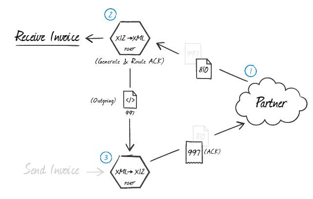
As shown in the illustration above, after a trading partner sends a message expecting an acknowledgment (1), the X12 connector in X12 to XML mode that parses the document automatically generates an ACK (2). This ACK is an XML file containing the transactional information relevant for the transaction. Then, this XML acknowledgment is routed back to an X12 connector in XML to X12 mode (3) so that the interchange headers (and any other X12 party agreement settings) are applied before the ACK is sent back to the trading partner.
Master-Detail Hierarchy: Translating HLLoops
In EDI documents, most hierarchical relationships are represented by the order of EDI segments. Some EDI structures, like HLLoops (which are found in Advance Shipment Notifications, or X12 856s), do not follow this convention and instead have the hierarchical relationships embedded in the EDI element data itself. This can make it difficult to preserve these hierarchical relationships when converting the EDI data to XML.
The X12 connector supports preserving hierarchical relationships in HLLoops via the Nest Loops setting in the Advanced Settings portion of the Advanced tab. When enabled, the connector parses the elements in the HLLoop segments to determine which segments “belong to” other segments in a hierarchical relationship. These hierarchical relationships are reflected in the output XML as parent-child relationships; in other words, this setting converts hierarchy implied by the EDI content into hierarchy represented by the XML structure.
This section explains how hierarchy is encoded in HLLoop data, and how this hierarchy is converted into XML when Nest Loops is enabled.
HLLoop Hierarchy
All HL segments have two values that help establish hierarchy:
- an Id value, which identifies the current HL segment (this value is stored in HL01, or the first element in an HL segment)
- a parent-Id value, which identifies the current HL segment’s hierarchical parent (this value is stored in HL02, or the second element in an HL segment)
For example, an HL segment has an Id value of ‘2’. If the next HL segment should “belong to” this prior segment in a hierarchical relationship, then the next HL segment’s parent-Id should also be ‘2’.
If an HL segment’s parent-Id is ‘0’, the segment does not have a parent (it is at the top level of the hierarchy).
HLLoop Example
To further clarify the hierarchical relationships in HLLoop data, take the following EDI snippet as sample input (only the lines beginning with HL are relevant to determining the data hierarchy; the remaining segments are included to more closely represent actual EDI data):
HL*1*0*S      // First HL loop, the shipment loop
TD3*RR*SEAU*1234567
HL*2*1*O      // Second HL loop, the order loop
PRF*PO111111
HL*3*2*P      // Third HL loop, the first package loop
MAN*UC*PACKAGE1
HL*4*3*I      // Fourth HL loop, the first item loop
MAN*UC*ITEM_1
HL*5*3*I      // Fifth HL loop, the second item loop
MAN*UC*ITEM_2
HL*6*2*P      // Sixth HL loop, the second package loop
MAN*UC*PACKAGE_2
HL*7*6*I      // Seventh HL loop, the third item loop
MAN*UC*ITEM_1
HL*8*6*I      // Eighth HL loop, the fourth item loop
MAN*UC*ITEM_3
In this data, the second HL segment “belongs to” the first HL segment in a hierarchical relationship. This can be determined by looking at the HL01 and HL02 values for these segments:
- The HL01 (Id) value for the first HL segment is ‘1’
- The HL02 (parent-Id) value for the second HL segment is also ‘1’
The same process of matching parent-Id values to Id values can be used to determine all of the hierarchical relationships in the data.
Converting HLLoop Hierarchy to XML
When Nest Loops is enabled, the X12 connector handles the conversion of HL hierarchy to XML hierarchy automatically. The connector parses the HL01 and HL02 element values from the EDI input and ensures that XML elements are appropriately nested (indented) inside the elements representing their parents.
To see how the HL hierarchy is converted into XML hierarchy, the following XML output is generated from the above sample HL data when Nest Loops is enabled:
<HLLoop1_S>
  <HL><HL01>1</HL01><HL02>0</HL02><HL03>S</HL03></HL>
  <TD3><TD301>RR</TD301><TD302>SEAU</TD302><TD303>1234567</TD303></TD3>
  <HLLoop1_O>
    <HL><HL01>2</HL01><HL02>1</HL02><HL03>O</HL03></HL>
    <PRF><PRF01>PO111111</PRF01></PRF>
    <HLLoop1_P>
      <HL><HL01>3</HL01><HL02>2</HL02><HL03>P</HL03></HL>
      <MAN><MAN01>UC</MAN01><MAN02>PACKAGE1</MAN02></MAN>
      <HLLoop1_I>
        <HL><HL01>4</HL01><HL02>3</HL02><HL03>I</HL03></HL>
        <MAN><MAN01>UC</MAN01><MAN02>ITEM_1</MAN02></MAN>
      </HLLoop1_I>
      <HLLoop1_I>
        <HL><HL01>5</HL01><HL02>3</HL02><HL03>I</HL03></HL>
        <MAN><MAN01>UC</MAN01><MAN02>ITEM_2</MAN02></MAN>
      </HLLoop1_I>
    </HLLoop1_P>
    <HLLoop1_P>
      <HL><HL01>6</HL01><HL02>2</HL02><HL03>P</HL03></HL>
      <MAN><MAN01>UC</MAN01><MAN02>PACKAGE2</MAN02></MAN>
      <HLLoop1_I>
        <HL><HL01>7</HL01><HL02>6</HL02><HL03>I</HL03></HL>
        <MAN><MAN01>UC</MAN01><MAN02>ITEM_1</MAN02></MAN>
      </HLLoop1_I>
      <HLLoop1_I>
        <HL><HL01>8</HL01><HL02>6</HL02><HL03>I</HL03></HL>
        <MAN><MAN01>UC</MAN01><MAN02>ITEM_3</MAN02></MAN>
      </HLLoop1_I>
    </HLLoop1_P>
  </HLLoop1_O>
</HLLoop1_S>
It is difficult to parse the difference at a glance, but the key thing to notice is that HLLoop segments are not contained in other segments (in other words, they have a parent-child relationship in the XML) in accordance with the HL01 and HL02 values from the original data.
Macros
ファイルの命名規則にマクロを使用することで、組織の効率とデータの文脈的理解を高めることができます。マクロをファイル名に組み込むことで、識別子、タイムスタンプ、ヘッダー情報などの関連情報を動的に含めることができ、各ファイルに有益なコンテキストを付与できます。これにより、組織にとって重要な詳細をファイル名に反映させることができます。
CData Arc はこれらのマクロをサポートしており、すべて次の構文を使用します:%Macro%
| Macro | 説明 |
|---|---|
| ConnectorID | コネクタのConnectorID を返します。 |
| Ext | コネクタが処理中のファイルの拡張子を返します。 |
| Filename | コネクタが処理中のファイルのファイル名(拡張子を含む)を返します。 |
| FilenameNoExt | コネクタが処理中のファイルのファイル名(拡張子なし)を返します。 |
| MessageId | コネクタがアウトプットするメッセージのMessageId を返します。 |
| RegexFilename:pattern | コネクタで処理中のファイルのファイル名にRegEx パターンを適用します。 |
| Header:headername | コネクタが処理中のメッセージのヘッダー(headername)の値を返します。 |
| LongDate | システムの現在の日時を長い形式(例:Wednesday, January 24, 2024)で返します。 |
| ShortDate | システムの現在の日時をyyyy-MM-dd 形式(例:2024-01-24)で返します。 |
| DateFormat:format | システムの現在の日時を指定されたフォーマット(format)で返します。使用可能な日付フォーマットについては、サンプル日付フォーマット を参照してください。 |
| Vault:vaultitem | 指定されたvault 項目の値を返します。 |
例
%Ext% や%ShortDate% などの引数を必要としないマクロもありますが、引数を必要とするマクロもあります。引数を渡すマクロはすべて次の構文を用います:%Macro:argument%
以下は、引数を渡すマクロの例です。
- %Header:headername%:
headernameはメッセージのヘッダー名です。 - %Header:mycustomheader% は、インプットメッセージで設定された
mycustomheaderヘッダーの値を返します。 - %Header:ponum% は、インプットメッセージで設定された
ponumヘッダーの値に対応します。 - %RegexFilename:pattern%:
patternは正規表現パターンです。例えば、%RegexFilename:^([\w][A-Za-z]+)%はファイル名の最初の単語と照合し、大文字と小文字を区別せずに結果を返します(test_file.xmlはtestに変換されます)。 - %Vault:vaultitem%:
vaultitemは、vault のアイテム名です。例えば、%Vault:companyname%はVault に保存されているcompanynameアイテムの値を返します。 - %DateFormat:format%:
formatは使用可能な日付フォーマットです(詳細はサンプル日付フォーマット を参照してください)。例えば、%DateFormat:yyyy-MM-dd-HH-mm-ss-fff%はファイルの日付とタイムスタンプを返します。
以下の例に示すように、より詳細なマクロを作成することもできます。
- 複数のマクロを1つのファイル名にまとめる:
%DateFormat:yyyy-MM-dd-HH-mm-ss-fff%%EXT% - マクロの外側にテキストを含める:
MyFile_%DateFormat:yyyy-MM-dd-HH-mm-ss-fff% - マクロ内にテキストを含める:
%DateFormat:'DateProcessed-'yyyy-MM-dd_'TimeProcessed-'HH-mm-ss%
X12 Operations
In addition to the Operations provided with Arc, connectors can provide operations that extend functionality into ArcScript.
These connector operations can be called just like any other ArcScript operation, except for two details:
- They must be called through the
connector.rscendpoint. - They must include an auth token.
For example, calling a connector operation using both of these rules might look something like this:
<arc:set attr="in.myInput" value="myvalue" />
<arc:call op="connector.rsc/opName" authtoken="admin:1j9P8v8b9K0x6g5R5t7k" in="in" out="out">
  <!-- handle output from the op here -->
</arc:call>
Operations specific to the functionality of the X12 connector are listed below.
x12Scan
Scans header values from the headers of an X12 document.
Required Parameters
- file: The path to the X12 file.
Optional Parameters
- format: The file format. The default value is ‘X12’.
Output Attributes
- InterchangeSenderIdQualifier: The interchange qualifier of the sender Id (ISA05).
- InterchangeSenderId: The interchange sender Id (ISA06).
- InterchangeReceiverIdQualifier: The interchange qualifier of the receiver Id (ISA07).
- InterchangeReceiverId: The interchange receiver Id (ISA08).
- InterchangeControlNumber: The value that uniquely identifies the EDI interchange (ISA13).
- FunctionalGroupSenderId: The functional group sender Id (GS02).
- FunctionalGroupReceiverId: The functional group receiver Id (GS03).
- DocumentType: The document type or transaction set Identifier code (ST01).
- StandardVersion The major version of the X12 Standard used in this interchange (e.g. 00401, 00501).
Common Errors
Following is a list of common errors, their causes, and the recommended solution. Please contact arcsupport@cdata.com for more information.
ERROR:
“Schema file not found ([schema major version] [schema document type])”
Cause
When Arc parses an X12 file, it first scans the file for the EDI version and document type to determine which schema to use during parsing. The application includes an extensive set of X12 schemas in JSON format. They are stored in the schemas folder in the application directory (next to the data folder).
This error indicates that the application could not find a schema file matching the major version and document type reported by the file.
If the [schema major version] value or [schema document type] value are missing in the error message, the EDI document does not contain the major version or document type.
Otherwise, this error indicates that the appropriate document schema is not included in the set of schema definitions automatically included with Arc.
Resolution
If the EDI file does not contain the schema major version or document type, contact the trading partner (or other source of the EDI document) and inform them that these values must be included in the message header.
Otherwise, find the appropriate schema version from our free download page here. Download the schema folder and place it in one of the following locations:
- Inside the schema folder on disk (for example,
<ConnectorDirectory>/Resources/Schemas/) - If a schema is used by multiple connectors, CData recommends you use a folder structure like this:
<ApplicationDirectory>/schemas/<type>_schemas/<major version>. In this example,<type>should bex12.
ERROR:
“The segment at line [line number] with tag [segment name] is not in a valid position in the specified schema ([schema major version] [schema document type]). This may indicate that the input file contains segments that are out of order.”
Cause
When Arc parses an X12 file, it first scans the file for the EDI version and document type to determine which schema to use during parsing. The application includes an extensive set of X12 schemas in JSON format, stored in the www\app_data folder of the root installation directory.
This error indicates that the parser encountered an EDI segment in the file that does not match the order of segments defined in the relevant document schema. This can indicate a few different issues:
- The EDI file was generated incorrectly by the trading partner
- The EDI file was generated using a different schema version than what is indicated in the file
- The EDI file was generated using a custom schema
Resolution
If the EDI file was generated using a custom schema, place the custom schema file (in JSON format) in the folder where Arc reads EDI schemas. The connector searches for schemas by checking the following locations in this order:
- Inside its folder on disk (for example,
<ConnectorDirectory>/Resources/Schemas/) - If a schema is used by multiple connectors, CData recommends you use a folder structure like this:
<ApplicationDirectory>/schemas/<type>_schemas/<major version>. In this example,<type>should bex12.
If the EDI file was not generated using a custom schema, there are two approaches to resolving the discrepancy between the EDI file generated by the partner and the EDI schema used to parse it.
- Manually edit the appropriate EDI schema file (found in the filepath above) to adjust the segment order so that it matches the partner’s EDI files. The error message indicates the line in the file where the segments diverge from the schema definition. Trace through the JSON definition of segment order until the divergence is found, and re-order the segments in the JSON to match the file provided by the partner.
- Contact the trading partner about the EDI file. Confirm that the file was generated according to the major version that is reported by the file, and explain that the order of the segments in the file is not recognized.
Which approach to use depends on your familiarity with EDI segments for the particular document type (to correctly edit the JSON schema according to the partner’s file) and the partner’s flexibility (to adjust the EDI file in response to informing them about the error).